since a couple of month I’m following the project. @Stuart Thanks a lot for your excellent work. The Videos are amazing and offer highly professional educational input. The forum and it’ members a source of inspiration. Thanks for all the information.
Right now I’m getting prepared to build a LiFePo battery as a DC-Store for our photovaltaic system. CATL’s Natrium based Batteries are not ready for the mass market yet. As a first initial pack, i will probably start with a 16 cells each 280Ah/3.3V (16S1P). Since I’m based in Germany and don’t want to go through direct shipping hassle from China, I prefere ordering via NKON (Eve LF280K v3 Prismatic 280Ah - LiFePO4 - 3.2V A-grade - Prismatisch - LiFePO4 - Wiederaufladbare Batterien | NKON). Current prices are abount 115€ to 120€ per cell.
There are a couple of projects and links in the internet that offer design and building proposals for cases (wood or metal based). Since I’d like to get a stackable design, I haven’t decided yet, which layout i will chose. But I’d like to choos diyBMS as the active balancing solution. It should allow to scale (one all-in-one board per powerpack, one controller-board in the master).
I will have time to solder and experiment in my spare time. So I’m willing to get my hands dirty on that.
Has anyone already implemented such an installation? Any advices?
What is the latest all-in-one board and a suitable controller?
I have the following problem and can not solve it for four days:
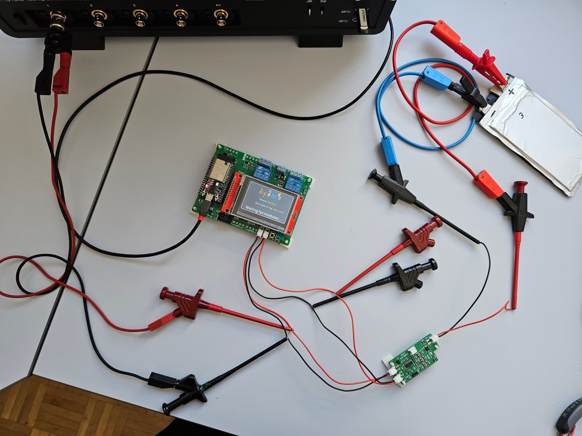
The modules are not recognized. The controller stays in the “Waiting for Modules…” state and sometimes restarts.
Initial situation:
Controller & modules (V4.5) partially assembled ordered from JLCPCB - Only Attiny1624, INA229 & connectors soldered by myself. I checked the solder joints and alignment of the ICs and could not find any fault. Component D2 on the modules has the correct orientation.
ControllerBoardTest program loaded on board via PlatformIo. The boardtest was successful incl. Tx & Rx communication (Led flashes green at the end and relays switch every second). No errors appeared in Serial Monitor).
Website is accessible and settings can be made.
Modules were programmed via an Arduino Uno with AVRDUDESS. (according to the manual DIY UPDI USB programmer which can be made with cheap hardware)
Firmware: module_fw_V450_10K_ATtiny1624_450_e0_h0_l0.hex
I also wrote a blink program for LED D4 on the module to test the UPDI programmer. Worked with every module.
When module is attached to power supply, LED D4 blinks four times, then twice every 8 seconds. As soon as the controller is attached the LED stays off.
Tested with 10 modules (either in 1S1P or 2S1P configuration). Tx to Rx rule was followed for the cables. Tested with and without temperature sensor connected.
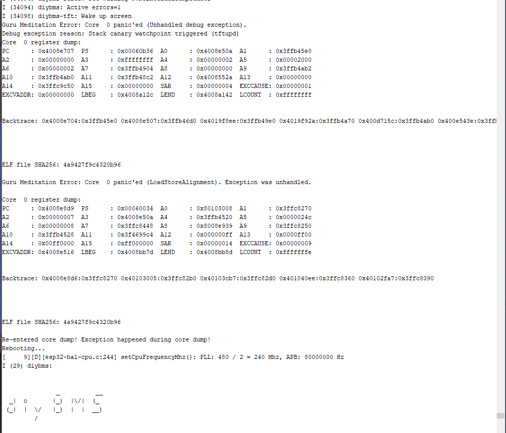
Controller randomly restarts at least every 2 minutes (it doesn’t matter if a module is connected or not) after the following error code:
Guru Meditation Error: Core 0 panic’ed (Unhandled debug exception).
Debug exception reason: Stack canary watchpoint triggered (tftupd)
Core 0 register dump:
PC : 0x4008e500 PS : 0x00060b36 A0 : 0x4008552a A1 : 0x3ffb48d0
A2 : 0x00000000 A3 : 0x00000000 A4 : 0x3ffb4ba0 A5 : 0x00000000
A6 : 0xffffffff A7 : 0x00000000 A8 : 0x00000000 A9 : 0x00000000
A10 : 0x3ffb49a0 A11 : 0x0000002a A12 : 0x00000064 A13 : 0x3f4835f8
A14 : 0x00000001 A15 : 0xff000000 SAR : 0x0000000c EXCCAUSE: 0x00000001
EXCVADDR: 0x00000000 LBEG : 0x4008bb7d LEND : 0x4008bb8d LCOUNT : 0xffffffff
When starting up the controller, the following error is displayed, but it does not prevent the controller from starting up.
I (5605) diybms-set: Load WIFI config from FLASH - return 1
I (5606) diybms-set: IP=0,GW=0
I (5606) diybms: Wifi Config: SSID:Mau Galaxy, Manual Config:0
I (5609) diybms: Manual IP:0.0.0.0, Netmask:0.0.0.0, GW:0.0.0.0, DNS1:0.0.0.0, DNS2:0.0.0.0
I (5617) diybms: Checking for /diybms/wifi.json
E (5624) diybms: Error deserialize JSON
I (5625) diybms-set: Load config
I (5628) diybms-set: Count: UsedEntries = (135), FreeEntries = (495), AllEntries = (630)
E (5636) diybms-set: Error (ESP_ERR_NVS_NOT_FOUND) opening NVS handle
Controller then changes to the status: “Waiting for Modules…”
What I have already tried:
Programming the ESP32 several times via the Pyflasher with the latest firmware “esp32-controller-firmware-complete.bin” (Compiled_Firmware_2023-09-12-10-49). I also tried with an older version, doesn’t work either. Controller firmware upgrade via the website with the file “esp32-controller-firmware-over-the-air.bin” did not make any difference either.
Programming the modules several times with the versions V450_ 2K4, 5K & 10K.
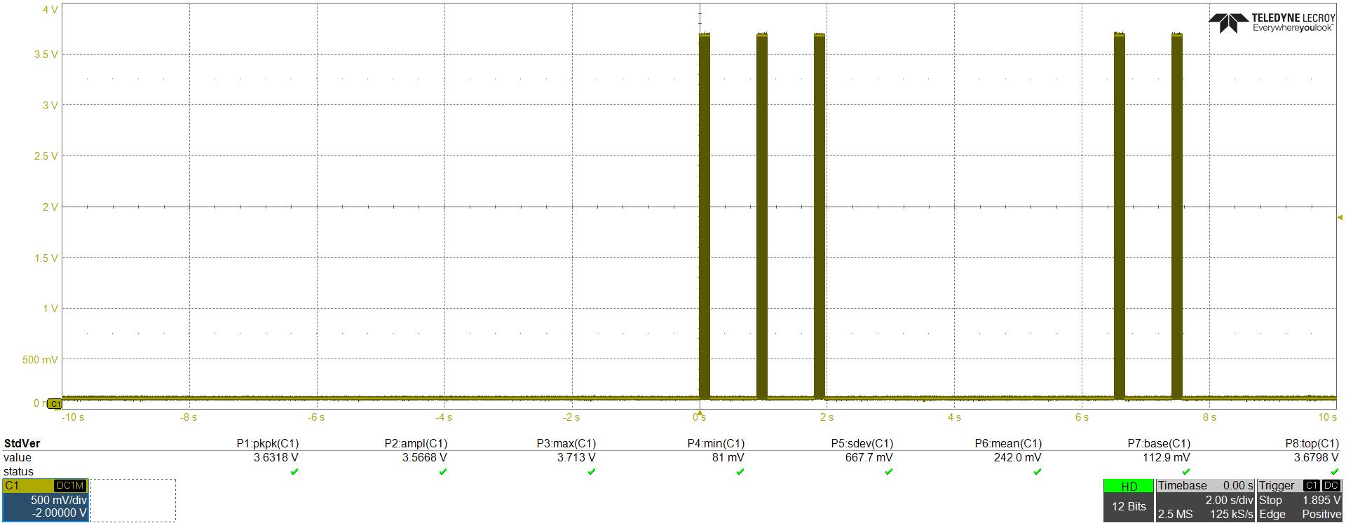
With an oscilloscope I tried to narrow down the error via the Tx/Rx communication:
1st measurement: Direct connection from Tx to Rx at the controller: Transmission is OK (With test program, as well as the normal program).
2nd measurement: Between controller Tx and module Rx: Transmission is OK
So it is clear that something is wrong with the module.
Do you have any tips what I could try to fix the error with the controller and the error with the module?
I will also try the UPDI programming via a USB-Serial FTDI in the next week, as soon as I get the material.
Solved
It was the communication speed, which i didn’t set in the web interface (More → Settings → Modules & Banks). I set it to 10K and it worked (with the matching Firmware installed: module_fw_V450_10K_ATtiny1624_450_e0_h0_l0.hex).
Since then there are also no restarts of the controller.
Thanks Stuart for your help and your effort for this project!
@stuart Status DIYBMS 16S Prototype
it has been 2 month now, that you released your 2nd video (https://www.youtube.com/watch?v=RwrlYUxnfZ0) for the new and upcoming all in one board (prototype 3). I just wanted to ask, if there is a new status?
Please don’t get me wrong, I’m not putting pressure on your onging development. But since I’m in the start-up process, this board would be ecactly what I want choose. You said, to solder the chips is quite difficult and time consuming. I’m not affraid to order the needed equipment (microscope, hot air, solder paste, flux, isopropyl alcohol). Mayby a small tripod for a mobile can do the trick for the microscope problem. But a tip from based on your experience is very well welcome.
Did the hardware design stabelize meanwhile? Is it good enough for first tinkering? I know about the ordering problem (need a minimung of 5 entities from JLC). But to stack two or three powerbanks, I will end up to need 3 anyways. May we can do shared orders?
To build a (probably stackable) powerBasket, I would like to base my tinkering on your metal case design. But it needs to be adapted for two rows (5 cells each). That will make it possible to stack them in the basement (think of a 19’’ rack solution).
Can you share the cat source-files? Do you have sugguestions to improve a rebuild? Probably others may be interested as well. Thanks.
I’m happy with the 16S modules (all-in-one) and just preparing the next video for its release.
I’m not planning to change the board design from what it is now. There was a small change to the firmware released last week for the temperature sensors.
Any thougths of adding a capacitor for the power supply of the Master? Especially when adding a TFT screen? Not sure if my USB cable is bad, or just needs ot add that capacitor
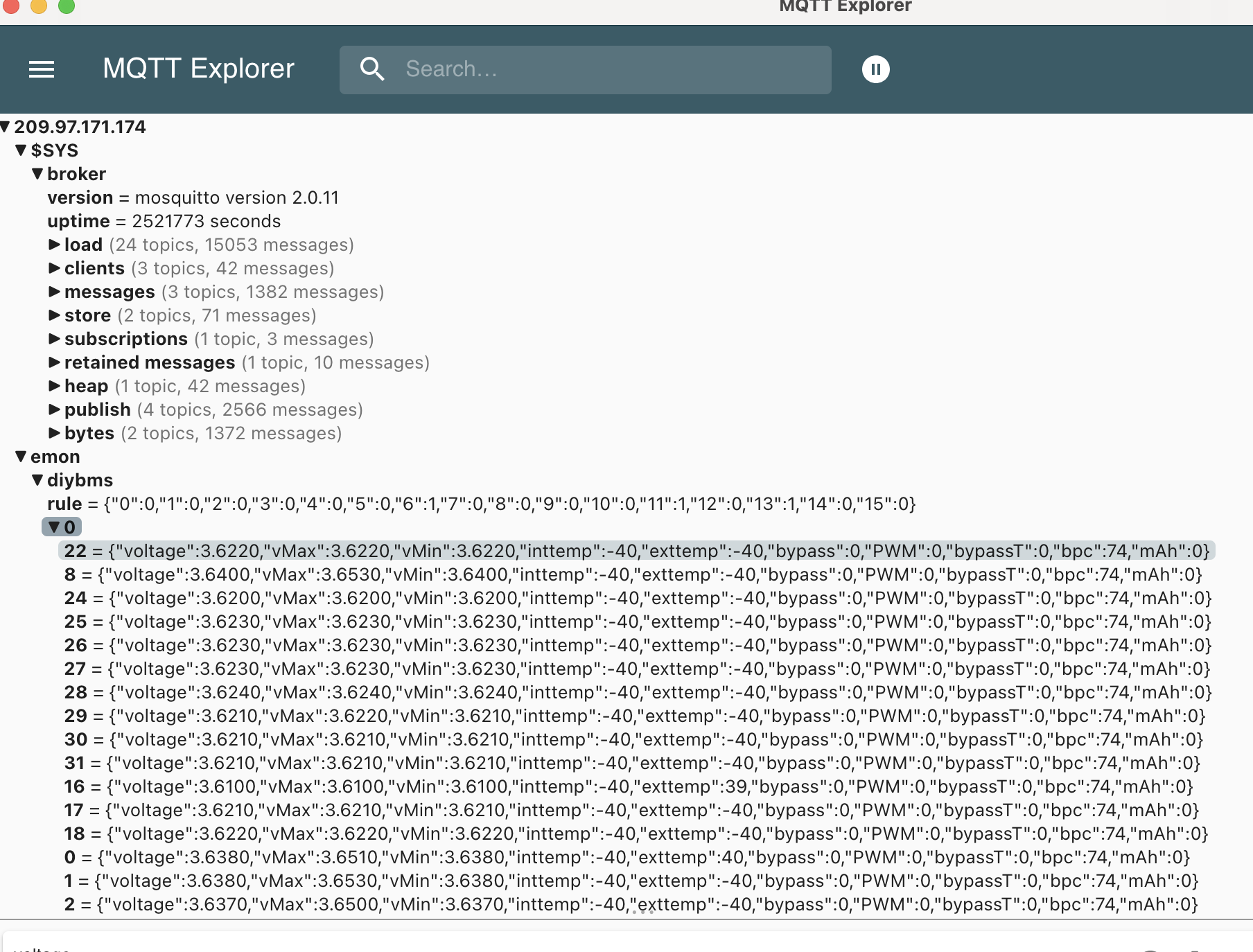
So, we have 2 52v batteries in series so far, getting our 100v on the BMS screen, and on the local monitor and on MQTT, but, the webapp only works locally, is there a way to get it to be viewable online through the cloud? not just a local IP address? the MQTT works fine in cloud.
I have a friend with a controller that doesn’t work, he sent it to me and at startup I get this error message, what could be causing it?
In board version 4.2, what is the function of jumper j13?
After several tests I have seen that it does not work with the screen and without the screen it works correctly, I have tried with other screens to rule out a fault in the screen and the problem is reproduced with any screen. I think it may be another problem, any ideas?
Same error with TFT that worked on old controller. Without the TFT it does NOT go into the boot loop.
               _          __
  _|  o       |_)  |\/|  (_
 (_|  |  \/   |_)  |  |  __)
         /

CONTROLLER - ver:169a4ea838986b107de2cf4abc0ed219f89c2bbc compiled 2023-09-12T10                                                                                                                          :47:12.660Z
ESP32 Chip model = 1, Rev 3, Cores=2, Features=50
I (36) diybms-hal: Configure I2C
I (38) diybms-hal: Scanning i2c bus
I (43) diybms-hal: Found i2c device at address 0x21
I (54) diybms-hal: Found TCA6416A
I (57) diybms: ** Controller changed state from Unknown to PowerUp **
I (413) diybms-set: nvs_flash_init
I (414) diybms-hal: CAN driver installed.  Filter=1621098496 Mask=6291455
I (415) diybms-hal: CAN driver started
I (422) diybms: LittleFS mounted, total=524288, used=139264
I (518) diybms: Mounting SD card
[  1026][W][sd_diskio.cpp:104] sdWait(): Wait Failed
[  1026][W][sd_diskio.cpp:512] ff_sd_initialize(): sdWait fail ignored, card ini                                                                                                                          tialize continues
[  1028][W][sd_diskio.cpp:516] ff_sd_initialize(): GO_IDLE_STATE failed
[  1035][E][sd_diskio.cpp:805] sdcard_mount(): f_mount failed: (3) The physical                                                                                                                           drive cannot work
[  1543][W][sd_diskio.cpp:104] sdWait(): Wait Failed
[  1543][E][sd_diskio.cpp:126] sdSelectCard(): Select Failed
E (1536) diybms-hal: Card mount failed


Press SPACE BAR to enter console WiFi configuration....


....................

No key press detected
I (6547) diybms-set: Load WIFI config from FLASH - return 1
I (6548) diybms-set: IP=0,GW=0
I (6548) diybms: Wifi Config: SSID:bering, Manual Config:0
I (6551) diybms: Manual IP:0.0.0.0, Netmask:0.0.0.0, GW:0.0.0.0, DNS1:0.0.0.0, D                                                                                                                          NS2:0.0.0.0
I (6559) diybms-set: Load config
I (6562) diybms-set: Count: UsedEntries = (82), FreeEntries = (548), AllEntries                                                                                                                           = (630)
E (6570) diybms-set: Error (ESP_ERR_NVS_NOT_FOUND) opening NVS handle
I (6576) curmon: Chip=INA229, Revision=1
I (6680) diybms: Onboard/internal current monitoring chip available
I (6680) curmon: RSHUNT=0.00033333, CURRENT_LSB=0.00028610, R_SHUNT_CAL=5000
W (6682) curmon: WARNING: True Max Current Measurable 122.88 Amps
I (6688) curmon: RECALC: RSHUNT=0.00033333, CURRENT_LSB=0.00023437, R_SHUNT_CAL=                                                                                                                          4096
D (6698) diybms: Setup RS485
D (6698) diybms: Configure RS485
I (6703) diybms: ** Controller changed state from PowerUp to Stabilizing **
D (6708) diybms: starting wifi_init_sta
I (6722) diybms: WIFI SSID: bering
D (6781) diybms: tca6416a_isr
I (6834) diybms: Hostname: DIYBMS-00CA719C
D (6835) diybms: wifi_init_sta finished
I (6835) diybms: TFT screen is INSTALLED
D (6838) diybms: total_free_byte=168760 total_allocated_byte=126420 largest_free                                                                                                                          _blk=110580 min_free_byte=168700 alloc_blk=369 free_blk=7 total_blk=376
I (14138) diybms-tft: Wake up screen
I (16906) diybms: Request time from time.google.com
I (16907) diybms: Timezone=UTC0DST0
I (16909) diybms: The current date/time is: Thu Jan  1 00:00:43 1970
I (16937) diybms: You can access DIYBMS interface at http://DIYBMS-00CA719C.loca                                                                                                                          l or http://192.168.1.50
I (16939) diybms-tft: Wake up screen
I (17006) diybms-rules: Set error 4:WaitingForModulesToReply
I (17506) diybms-rules: Set warning 9:NoExternalTempSensor
I (17506) diybms: Active errors=1
I (17509) diybms-tft: Wake up screen
I (19502) diybms: Task 1
I (20507) diybms-rules: Set error 4:WaitingForModulesToReply
I (20508) diybms-rules: Set warning 9:NoExternalTempSensor
I (20508) diybms: Active errors=1
I (20512) diybms-tft: Wake up screen
I (23510) diybms-rules: Set error 4:WaitingForModulesToReply
I (23511) diybms-rules: Set warning 9:NoExternalTempSensor
I (23511) diybms: Active errors=1
I (23515) diybms-tft: Wake up screen
Guru Meditation Error: Core  0 panic'ed (Unhandled debug exception).
Debug exception reason: Stack canary watchpoint triggered (tftupd)
Core  0 register dump:
PC      : 0x4008e502  PS      : 0x00060336  A0      : 0x4008552a  A1      : 0x3f                                                                                                                          fb4700
A2      : 0x00020000  A3      : 0x0002e000  A4      : 0x0000a000  A5      : 0x00                                                                                                                          000000
A6      : 0x00ff0000  A7      : 0xff000000  A8      : 0xa0000000  A9      : 0xe0                                                                                                                          000000
A10     : 0x0000001c  A11     : 0x00000000  A12     : 0x00000000  A13     : 0x00                                                                                                                          000000
A14     : 0x3ffc9c50  A15     : 0x00000000  SAR     : 0x00000004  EXCCAUSE: 0x00                                                                                                                          000001
EXCVADDR: 0x00000000  LBEG    : 0x4008a12c  LEND    : 0x4008a142  LCOUNT  : 0xff                                                                                                                          ffffff


Backtrace: 0x4008e4ff:0x3ffb4700 0x40085527:0x3ffb47e0 0x4019f8ee:0x3ffb4af0 0x4                                                                                                                          019f92a:0x3ffb4b80 0x400d715c:0x3ffb4bc0 0x400e543e:0x3ffb4c30 0x400e5588:0x3ffb                                                                                                                          4cb0 0x400e5da7:0x3ffb4d30 0x400e610c:0x3ffb4e80


ELF file SHA256: 4a9427f9c4320b96

Rebooting...
ets Jul 29 2019 12:21:46