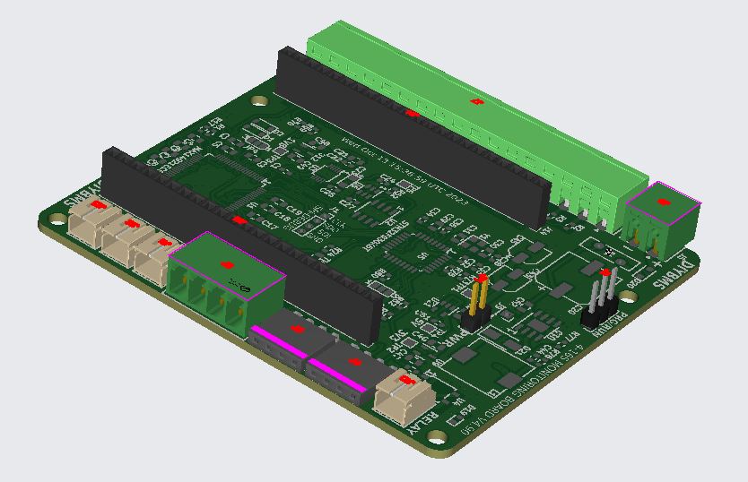
Pins are labeled per the DevKitC standard.
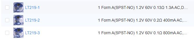
no stock of the LT219-1, are those other ones compatible?
i get the same error when i boot my esp without the 4.2 board connected
               _          __
  _|  o       |_)  |\/|  (_
 (_|  |  \/   |_)  |  |  __)
         /

CONTROLLER - ver:169a4ea838986b107de2cf4abc0ed219f89c2bbc compiled 2023-09-12T10                                                                                       :47:12.660Z
ESP32 Chip model = 1, Rev 1, Cores=2, Features=50
I (262) diybms-hal: Configure I2C
I (263) diybms-hal: Scanning i2c bus
I (267) diybms-hal: Found i2c device at address 0x20
I (270) diybms-hal: Found i2c device at address 0x38
I (277) diybms-hal: TCA6416A not fitted, assume v4.2 board
I (278) diybms-hal: Found TCA9534A
I (280) diybms-hal: Found TCA6408
I (281) diybms: ** Controller changed state from Unknown to PowerUp **
I (640) diybms-set: nvs_flash_init
I (642) diybms-hal: CAN driver installed.  Filter=1621098496 Mask=6291455
I (642) diybms-hal: CAN driver started
I (649) diybms: LittleFS mounted, total=524288, used=139264
I (745) diybms: Mounting SD card
[   842][W][sd_diskio.cpp:516] ff_sd_initialize(): GO_IDLE_STATE failed
[   843][E][sd_diskio.cpp:805] sdcard_mount(): f_mount failed: (3) The physical                                                                                        drive cannot work
E (790) diybms-hal: Card mount failed


Press SPACE BAR to enter console WiFi configuration....


....................

No key press detected
I (5794) diybms-set: Load WIFI config from FLASH - return 1
I (5795) diybms-set: IP=0,GW=0
I (5795) diybms: Wifi Config: SSID:..., Manual Config:0
I (5798) diybms: Manual IP:0.0.0.0, Netmask:0.0.0.0, GW:0.0.0.0, DNS1:0.0.0.0, DNS2:0.0.0.0
I (5807) diybms-set: Load config
I (5810) diybms-set: Count: UsedEntries = (244), FreeEntries = (386), AllEntries = (630)
I (5844) curmon: INA229 chip absent
I (5845) diybms: Onboard/internal current monitoring chip not installed
D (5847) diybms: Setup RS485
D (5847) diybms: Configure RS485
I (5851) diybms: ** Controller changed state from PowerUp to Stabilizing **
D (5856) diybms: starting wifi_init_sta
I (5879) diybms: WIFI SSID: ...
D (5926) diybms: tca6408_isr
I (5989) diybms: Hostname: ...
D (5990) diybms: wifi_init_sta finished
I (5990) diybms: TFT screen is INSTALLED
D (5993) diybms: total_free_byte=168356 total_allocated_byte=126800 largest_free_blk=110580 min_free_byte=168296 alloc_blk=371 free_blk=6 total_blk=377
I (12492) diybms-tft: Wake up screen
I (14903) diybms: Retry 1, connect to Wifi AP
I (15353) diybms-rules: Set error 4:WaitingForModulesToReply
I (17315) diybms: Retry 2, connect to Wifi AP
E (17360) diybms-mqtt: MQTT enabled. WIFI not connected
I (17849) diybms: Task 1
I (19728) diybms: Retry 3, connect to Wifi AP
I (20363) diybms-rules: Set warning 9:NoExternalTempSensor
I (20363) diybms: Active errors=1
I (20365) diybms-tft: Wake up screen
I (22142) diybms: Retry 4, connect to Wifi AP
E (22365) diybms-mqtt: MQTT enabled. WIFI not connected
I (23352) diybms: Task 2
I (23363) diybms-rules: Set error 4:WaitingForModulesToReply
Thank you for that! I found a board and esp32 combination that runs, so I am set for the near term.
You get free LCSC shipping if you order parts and a board from JLC at the same time, but agree, for that sort of cash, probably easier for them to solder it on.
Can you get some high res photos of the v4.6 boards you have so I can cross check?
shipping discount of up to 15$
A release today should fix this problem - it only appears to occur on newer revision 3 ESP32 chips.
You can upgrade as usual from GITHUB.
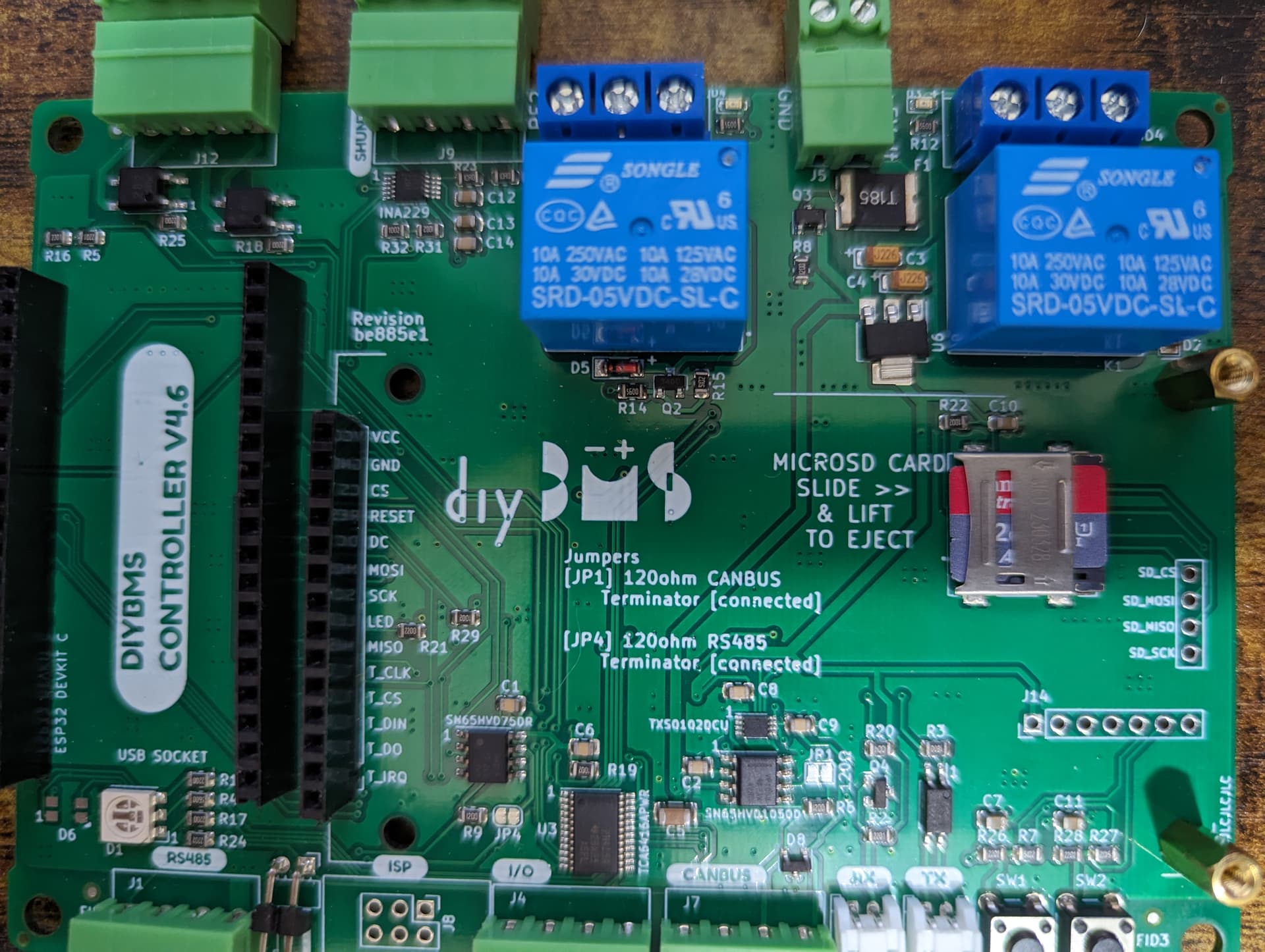
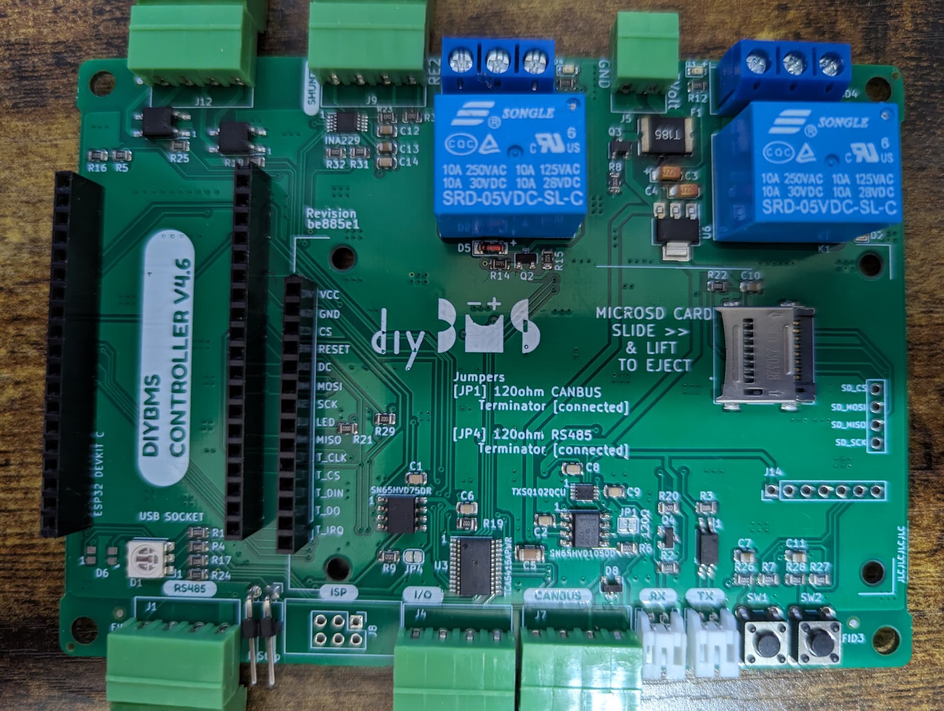
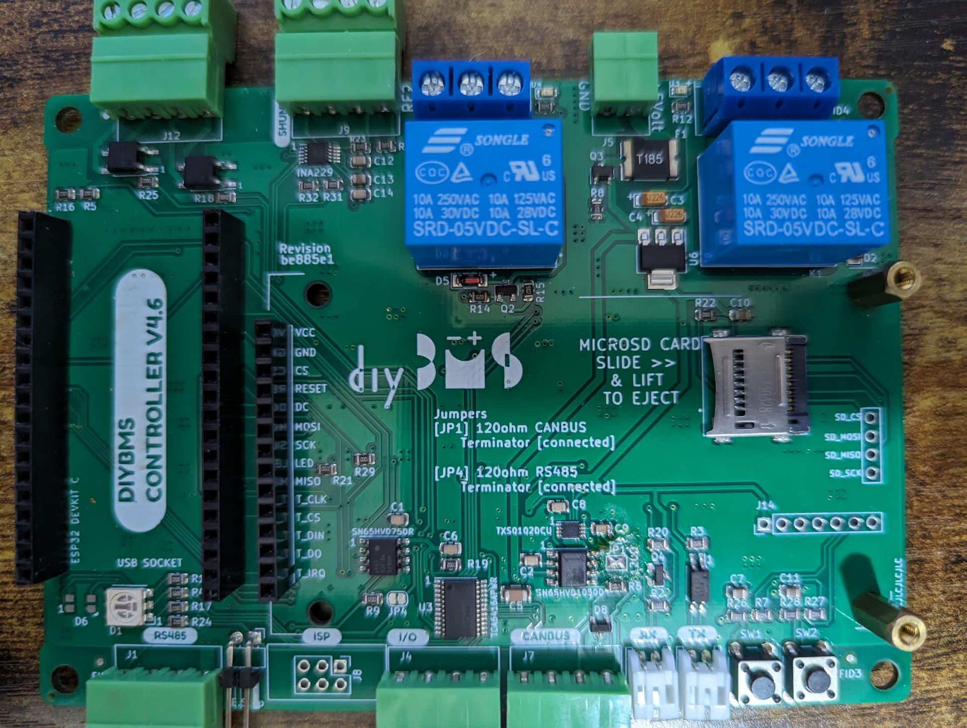
Did you solder on the SMD parts as well? I’ve released new code today which should solve the TFT issue, but you were still getting issues with i2c communication so that’s either a bad TCA6416 chip or a bad soldering joint near that chip.
@stuart
have you released the final stable version code for the all in one module?
is it DIYBMS-Release-Artifact-2023-10-12-13-40 the last stable, or is something coming after this?
There was a release for both all-in-one and controller yesterday @voltmeter
I have a problem with the Deye inverter and the BMS but I think I know now why the Deye does strange things.
I think the reson is that the Deye get via Can the information from the BMS that the SOC is 105%
I have NCR18650 Cels with a voltage range of 2,5 to 4,2V and 15 in series so voltage range is 37,5 to 63V
The actual voltage is 53,8x V, the BMS think that the SOC is 105%

How is the SOC calculated?
It maybe hase somthing to do with the Tail Current. I dont realy understand what a Tail current is. I thougt that this is the minimal charging current when the charge voltage is at max.
The datasheed of my cells say Charge Cut of at 4,2V and 65mA → 15*65mA = 1A
My setings:
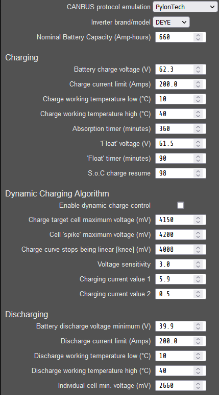
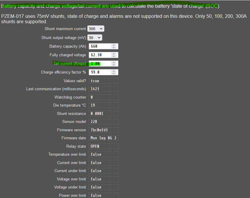
i have set my tail current to 10A
I had the tail current before at 13A, was the same.
Battery got discharged during night and is now at 52.84V → SOC is still at 105%
Its geting charged now (Deye is set to V-Bat)
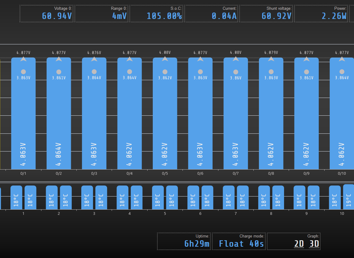
Values at 0755 - look on the Ah out and Ah in

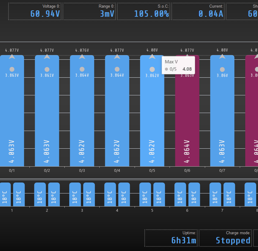
and now 5 minutes later

well I think I have to turn the shunt. Then the power input is input and not output

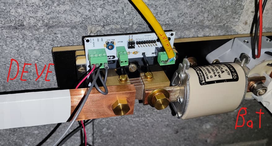
Dam, if this is, and I think it is, realy the reason it has cost me quit a lot of hours.
Just looked on the second board I have and there is such a nice silk screan text I totaly ignored (OK the shunt cover it).
The SoC is calculated based on amp-hour (energy) counting, as you have seen looks like the shunt battery connection is round the wrong way, a negative current reading is for discharge of the battery.
The SoC has a hardcoded limit of 105%, because it is possible to go over 100% until the system is calibrated properly and the first “real” 100% charge is reached.
I would set the tail voltage and current to be just under the maximum “battery charge voltage (V)” value - so 62.2V and I would also set the tail current between 5 to 10 Amps.
Once that voltage/current combination is reached the shunt will reset to 100% - although due to the way the system works (taking into account the “Charge efficiency factor %”) you will probably see 99%.
You can also manually reset the SoC using the settings in the “Utilities” page.
I would also recommend updating the shunt firmware if you are taking it apart.