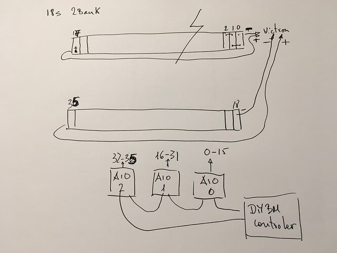
try to twist the voltage sense wires those from the shunt
maybe you get some external voltage into the wires
Maybe sharing the shunt for the internal and external current controller generated some kind of interference. I have left it only connected to the internal current controller and now at rest I have values that oscillate between +0.02A and -0.02A, which is a reasonable value.
Unfortunately it was only temporary, I have no-load values of 0.27A again so maybe it is because of a defective INA, maybe I will change it or use the external Curren Controls since I already have it installed in my battery system for a long time 2 years with excellent results.
someone has managed to connect a DIYBMS system with a Voltronic type inverter. What has been the cambus connection that has worked for this? I am referring to the pinout that the inverter must receive and which is logically different from that required for a Victron system.
I try to help a friend but despite more tests that he has carried out changing the pins to which CAM H and CAM L arrive, we cannot get the inverter to identify that it has an intelligent battery connected. of course jumper JP1 has been closed
I have seen that there is a branch on github GitHub - ruza87/diyBMSv4ESP32 at pylon_rs485
that solves the problem with Voltonic, this afternoon we are going to test it, but I suspect that it will not have compatibility with All in One, any ideas about it?
hi all
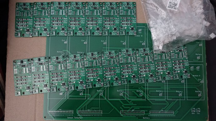
i have some parts for sale
17 modules v4.4 without attinys and one collection pcb max 5k com speed (if single board use then max 9,6k)
you have to buy and solder the attiny chips
45eur
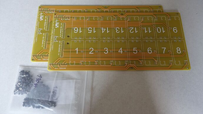
and two pcb for v4.5 modules with connectors to build a clean 14-16s system (max speed 10k)
20eur
location in germany, can send in eu
shipping cost are not incl.
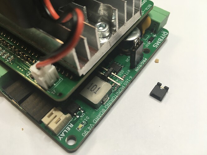
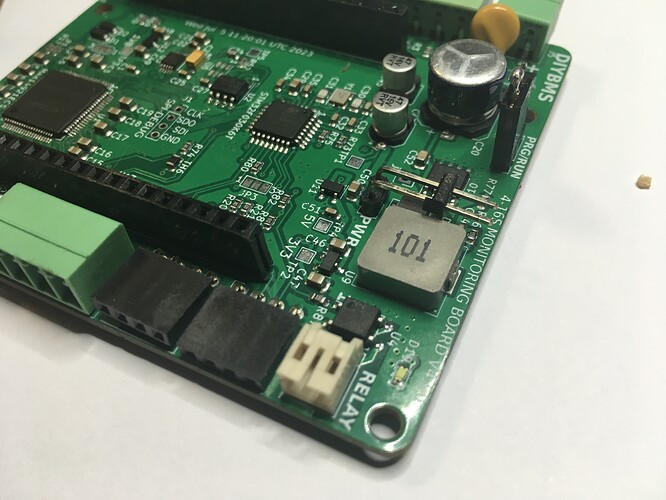
It would worry me that those 12V pins is so easy to touch and cause damage.
good warning, I’m going to insulate them with heat shrink until the contact tip
does somebody know how to add a rj45 connector to the esp that is used on the diy bms controller?
this is the only hardware in my network that uses wifi, i want to get rid of it and disable the wifi on my router.
Hi, the Topic we had somewere earlier as well.
Unfortunately the ESP32 on the DIYbms board does not have enough pins available.
May an enhancement could be, that in a next version the WT32ETH01 board could be used for the controller.
I love to use that controller in regards to exactly this topic, as Wifi is not that reliable.
Isolated high voltage & isolated current shunt based on ADS1115 - #2 by Chris87.
Quick question regarding the MQTT messages.
I havent figured out what does label stand for:
- emon/diybms/0/0 “pbc” = “Permissible Battery Current” = measured in “A”
What is this topic for:
- emon/diybms/output = output relays 1-4
Further i dont know the possible statuses or units:
- emon/diybms/0/0 “bypass” #I guess 0=off, 1=on
- emon/diybms/0/0 “PWM” #I guess %
- emon/diybms/0/0 “bpc”
- emon/diybms/modbus_A90 “valid” #I guess 0=off, 1=on for modbus
- emon/diybms/status “sendqlvl”
EDIT: By switching on a single brain cell i was able two answer questions myself.
@stuart
just watched the new firmware upgrade video for the controller.
fantastic work.
but as you said the float mode is not for everyone.
i have a full battery detection at 56V then my hot water heater starts. if i float then it would detect not enough charging power and will shut down so i wont use this.
but maybe in future it will be useful for me
can you add a new rule for the relay trigger to the shunt?
on at x %, off at x % and a delay timer when switched on.
(maybe additional setting the mV deviation, to ensure the battey is really full and need no longer balancing)
this could solve my problem with the voltage trigger for my hot water system
Have you run out of relays on the controller?
is there a rule for soc in the controller? have not noticed that.
Hi @Adas .
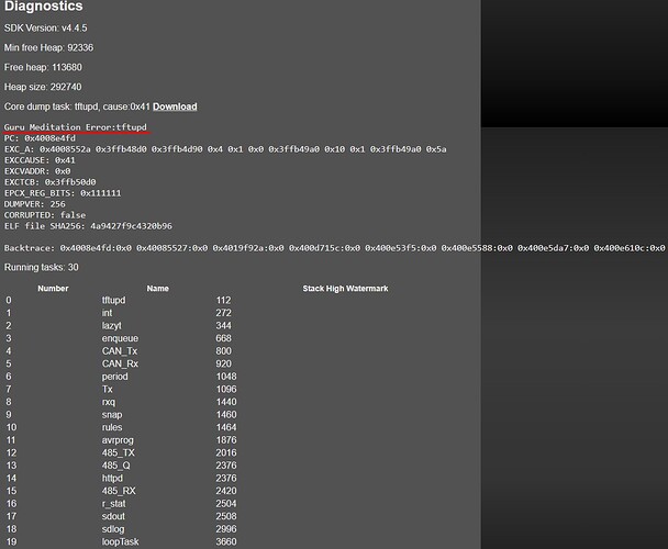
I’ve tried to make any “internal” errors more visible in the web interface. If you click the “download” link, it will clear this error out (just delete the downloaded file afterwards).
If this error keeps returning, then we can take a look.
I’d like to report some bugs:
- For me upgrading the controller from April 23’ firmware to September 23’ firmware did not work.
Upgrading “over the air” worked OK, unfortunately after the upgrade Wifi started to disconnect after few minutes after powering up and didn’t connect anymore until next reboot. - Also downgrading “over the air” from 09-23’ to 04-23’ didn’t work so finally (after many attempts) I downgraded “by hand” (NodeMCU Software) the to April 23 version with “wipe off” data.
This triggered an avalanche of problems with settings:
- I’m lost which window is for saving/restoring settings of rules, charge/discharge settings etc. I thought it was the right window in “Storage & Logging” but it seems I was wrong - uploading there prviously saved (by hand) setting file and restoring those settings (_cfg_20230913_133118.json) does not work.
- Restoring the left window settings also did not restore the settings.
Hi @philips, often a complete wipe of the firmware on the controller is a good idea.
However, I’m more concerned that the settings restore didn’t work.
Can you open a GitHub issue for this please, that’s the preferred way to get low level support.
Regards Stuart
Hi stuart and all the wonderful people here,
lookin for a way to monitor my nicd battery bank i found this:
How could this be implemented in your 16s design? (externally to make it simple, or replacing the balancer board).
From what i undertand you can use multiple inputs of the bms to get around the 4.5v limitation, and just find the sum of all the individual voltages.
Some components control the middle inputs to equalise the readings under 4.5v.
12v battery would use 3/4 inputs and 6v battery would use 2 inputs.
This would allow to monitor 12v lithium camper batteries, lead acid, agm, nicd and everything that you could think about…
Another question, the voltage limit is 65v does this mean you can only charge each cell to 4.06v in a 16s li.ion bank?
I would like to have a function in node RED that transforms all the data that arrives via mqtt from the controller into data that I can pass to Influx, especially the modbus_A90 data, and range of each bank data, since if I integrate directly to Influx, I do not receive this range of data .
But my knowledge is not enough to generate this function.
I copy it as I have it so that you can identify the errors I am making and, if necessary, suggest corrections.
Thank you very much in advance
const topic = msg.topic.split('/');
const message = topic[1];

var measurement = null;
var retentionPolicy = null;
var expiry = "";
var tags = "";
var data = "";

if (!isNaN(message)) {
    measurement = "series";
    tags = {    bank: message,
                series: topic[2].padStart(2, "0")
            };
    data = {    voltage: msg.payload.voltage,
                vMax: msg.payload.vMax,
                vMin: msg.payload.vMin,
                inttemp: msg.payload.inttemp,
                exttemp: msg.payload.exttemp,
                bypass: msg.payload.bypass,
                PWM: msg.payload.PWM,
                bypassT: msg.payload.bypassT,
                bpc: msg.payload.bpc,
                mAh: msg.payload.mAh
            };
    node.send([null, { topic: "diybms/series", bank: tags.bank, series: tags. series, payload: data}]);

} else if (message == 'status') {
    measurement = "status";
    tags = {};
    data = {    banks: msg.payload.banks,
                cells: msg.payload.cells,
                uptime: msg.payload.uptime,
                commserr: msg.payload.commserr,
                sent: msg.payload.sent,
                received: msg.payload.received,
                badcrc: msg.payload.badcrc,
                ignored: msg.payload.ignored,
                oos: msg.payload.oos,
                roundtrip: msg.payload.roundtrip,
                dynchargev: msg.payload.dynchargev,
                dynchargec: msg.payload.dynchargec
            };
} else if (message == 'modbus_A90') {
    if (!msg.payload.valid || msg.payload.valid == 0) return;
    measurement = "modbus_A90";
    tags = {};
    data = {    valid: msg.payload.valid,
                voltage: msg.payload.voltage,
                current: msg.payload.currentm,
                mAhIn: msg.payload.mAhIn,
                mAhOut: msg.payload.mAhOut,
                power: msg.payload.power,
                temperature: msg.payload.temperature,
                shuntmV: msg.payload.shuntmV,
                relayState: msg.payload.relayState,
                soc: msg.payload.soc
            };
    node.send([null, { topic: "diybms/modbus_A90", payload: data}]);
} else if (message == 'bank') {
    measurement = "bank";
    tags = { bank: topic[2] };
    data = { voltage: msg.payload.voltage };
} else return;

return [{measurement: measurement, retentionPolicy: retentionPolicy, payload: [data, tags]}, null];
Moderator’s comment & request:
For future reference, when posting code or output, please put 3 ‘backticks’ (normally found at the top left of the keyboard) on a line of their own before the code, and 3 more backticks also on a line of their own after the code:
```
code
```
If it is something like php you can add a language identifier after the first 3 backticks: ```php or even ```text if you don’t want any language markup applied.
