Only this range is used, so any shunt over 40.96mV will be clipped at the top end of the range. This isn’t normally a problem, as you shouldn’t be using a shunt at max. current rating - probably 30% less, so this works great on 50mV shunts.
75mV should will lose nearly half the range, so 50A should will stop around 25amps as reported.
why not use the adc range 0 ? is there a limitation on the controller itself or just a programing thing?
I’m asking because in my area 50mV are 25 euro /piece and 75 mV shunts are 2 euro , both for 50A.
Price is one of the concerns , but also I have 30 unused 75mV shunts.
Ok thank you for this. e843bcb23f6aa0b0b75df78a05d59a0f5dc46bc7 release appears to be this one
Leave the current monitor ATTINY code as it is for now, lets concentrate on the ESP32.
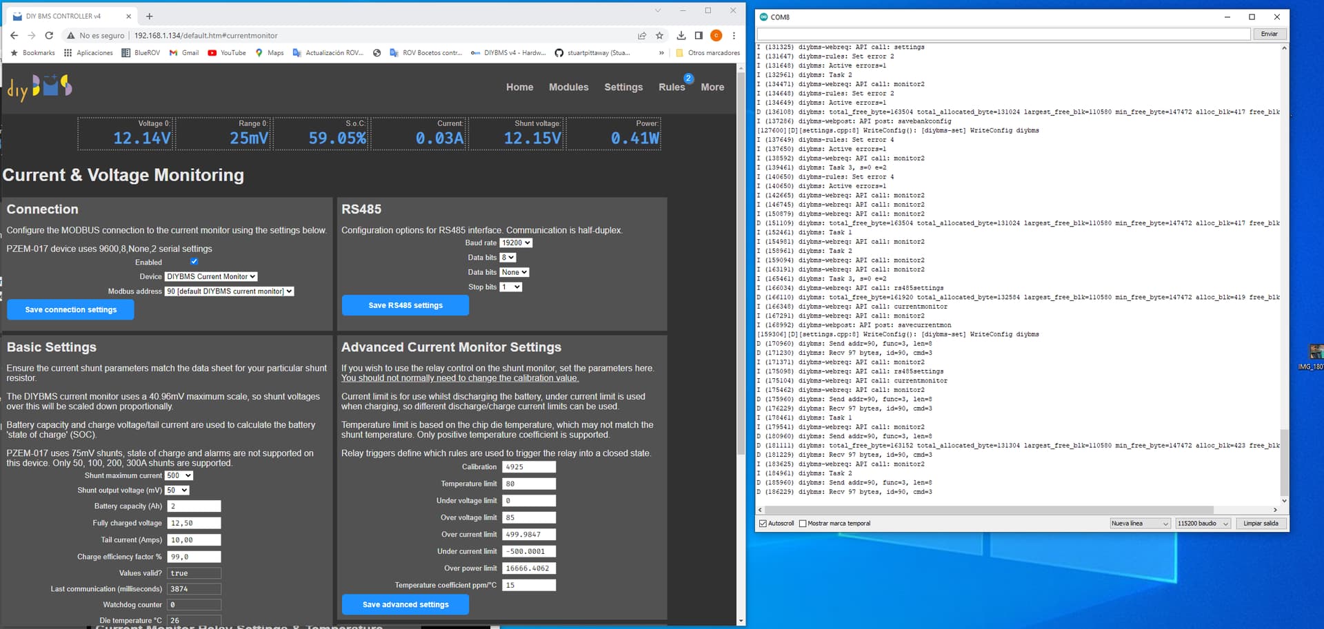
When you swapped to the latest code, did you double check all the settings for the module communication speed were correct? Did the graphs show in the display?
Did you double check the RS485 port settings and “DIYBMS EXTERNAL” shunt in the drop down list?
Can you take a look at the log messages on the USB serial port of the ESP32 please.
what if i change the vhunt register from 78125UL to 312500 UL.
is it going to work?
from :
// 78.125 nV/LSB when ADCRANGE = 1
    // Differential voltage measured across the shunt output. Two's complement value.
    // 20 bit value max = 1048575
    int32_t vshunt = readInt20(INA_REGISTER::VSHUNT);
    return (float)(((int64_t)vshunt) * 78125UL) / 1000000000.0;
to
// 312.5 nV/LSB when ADCRANGE = 1
    // Differential voltage measured across the shunt output. Two's complement value.
    // 20 bit value max = 1048575
    int32_t vshunt = readInt20(INA_REGISTER::VSHUNT);
    return (float)(((int64_t)vshunt) * 312500UL) / 1000000000.0;
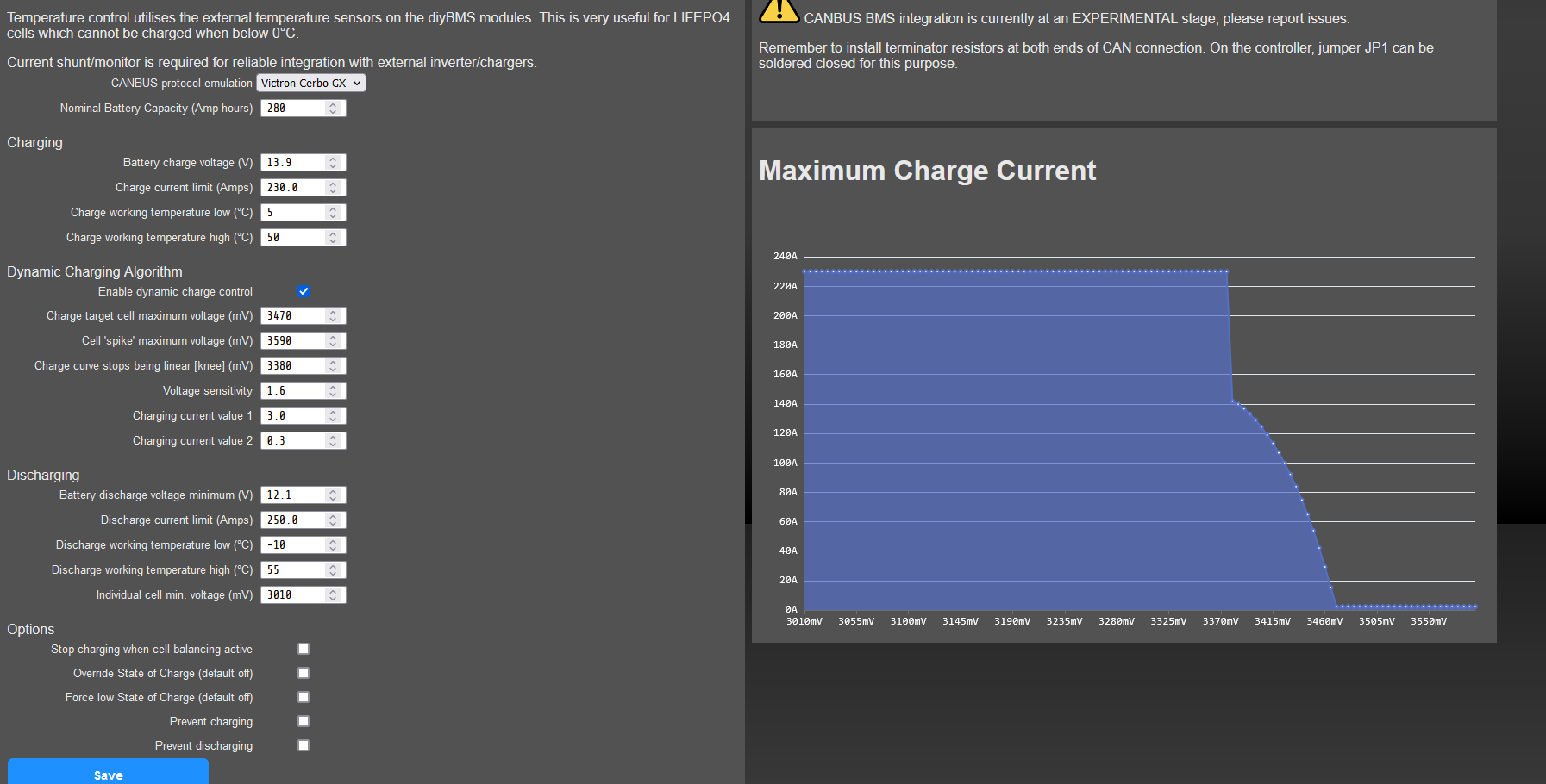
Not without a lot of other significant code changes. I did consider this, but felt it easier to ask people to use 50mA shunts. Typically people with 75mA shunts have high current ratings (500A+) so losing half the range, isn’t a problem.
If you have the time, I’d love a pull-request/submission to introduce those changes. You’d need to read through the data sheet, as its quite complex.
changes made to CurrentMonitorINA229.cpp file , or the whole controller code. I`m not very good at coding , but through trial and error I did managed to achieve what I wanted.
If is just that file , I would try.
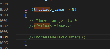
Thank you, sorry I forgot to say, I already managed to come to this conclusion! I commented out the two lines in the main source code file (as you can see below). I’ve been testing it for the last week and a half and it seems to be working well! Makes sense to not want to leave the screen on in a battery powered scenario but with an electric motorcycle when you’re drawing a couple of hundred amps from a 60V battery, an extra few mA at 5V isn’t so bad!
Thanks very much for making the source code available Stuart!
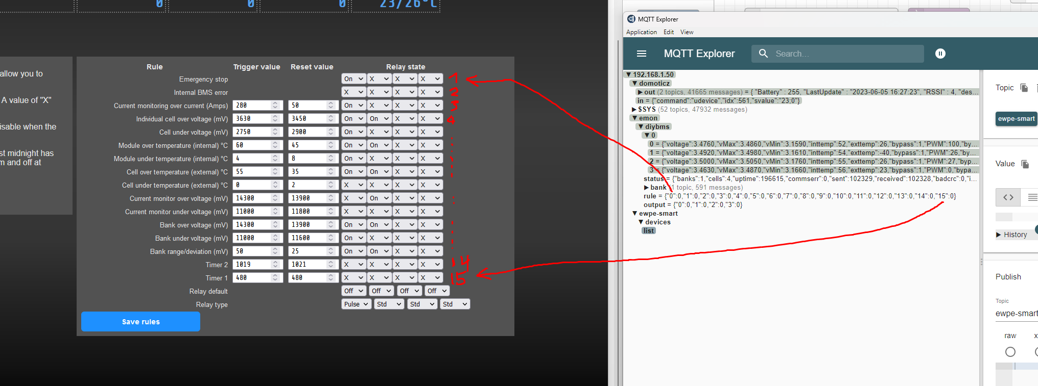
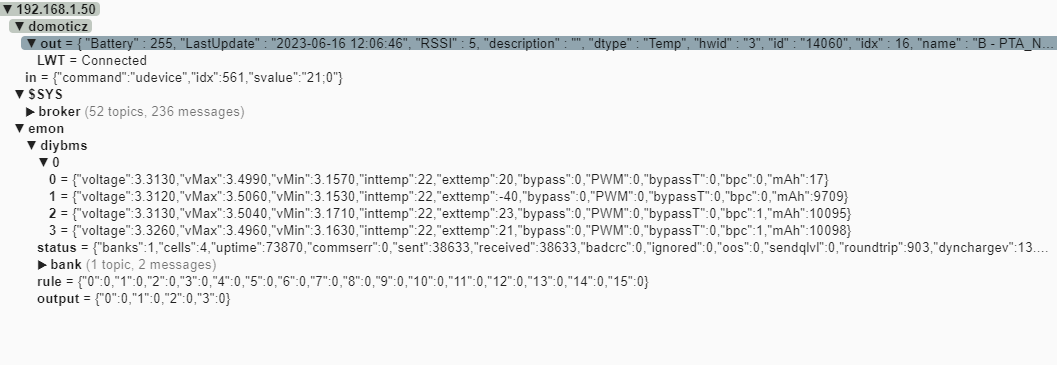
How to split Json message where instead of a string like : msg.payload.exttemp.toString()
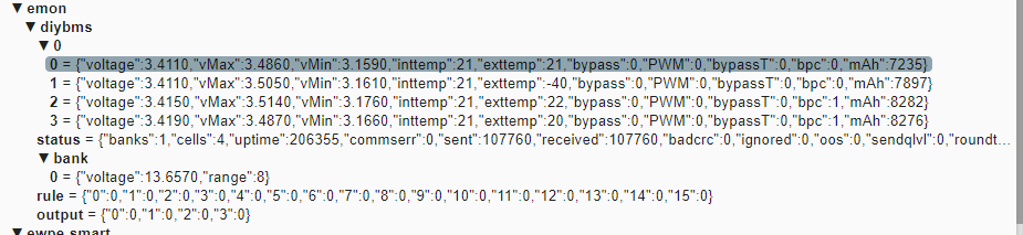
there is a number to split ? output = {"0":0, "1":0 }
The phrase : msg.payload.0.toString()
does not work. Is the “0”:0 a number, boolean, string ?
Thanks for help.
OK, I’ll answer myself
So the keys in the message shouldn’t be numbers but strings (as far as I know/read yesterday), so instead of : output = {"0":0, "1":0, "2":0 }
it should be: output = {"output0":0, "output1":0, "output2":0 }
In Nodered it is possible to change it using a function. Since I’m not familiar with Nodered and coding generally, I used for the first time ChatGPT to generate code and it worked This is what chatGPT generated:
// Get the incoming message payload
var payload = msg.payload;

// Create a new object to store the modified payload
var modifiedPayload = {};

// Iterate over the keys in the payload
for (var key in payload) {
    // Create the modified key with "rule" prefix
    var modifiedKey = "output" + key;

    // Assign the value to the modified key in the new object
    modifiedPayload[modifiedKey] = payload[key];
}

// Assign the modified payload to the output message
msg.payload = modifiedPayload;

// Return the modified message
return msg;
The outcome is: output = {"output0":0, "output1":0, "output2":0 }
and now its is possible to use:
Hi Guys,
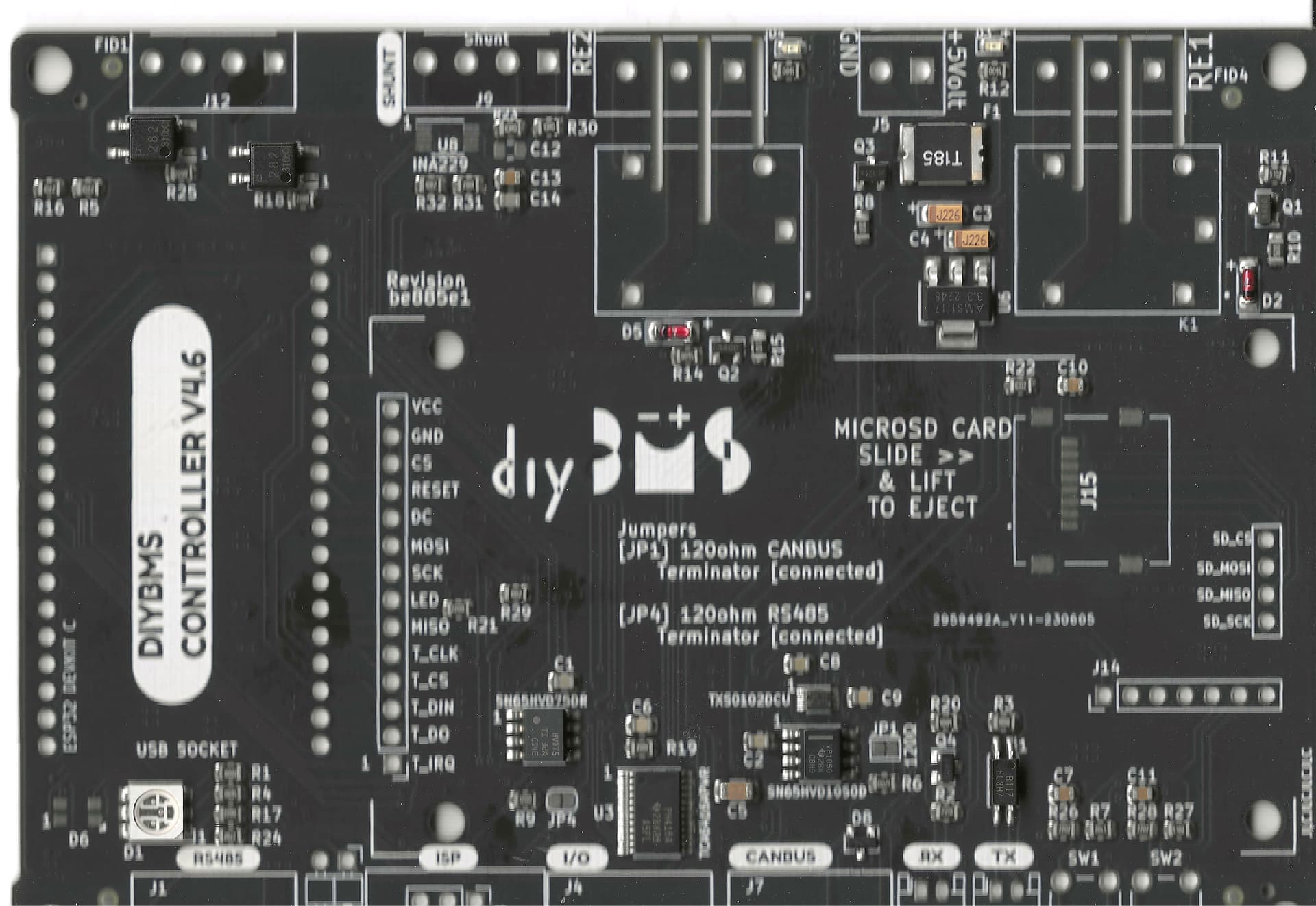
my second batch of controllers (4.6) arrived earlier. I soldered the esp32 to it connected everything like it worked with earlier controllers (4.2), but the controller can’t receive the module datapackets that are clearly being sent out. (The blue light is flashing on each module). Then at the last module the light flashes and nothing happens. I even bridged the TX and RX pins of the board directly but even the ignored errors weren’t there.
I use the 4.6 controller with release Release-2023-04-17-08-26.
The modules are version 4.40 with the software from early 2022.
I’ll attach a scan of an unpopulated board. Maybe you can spot something wrong?
Greetings Max.
Nothing is going to work properly until this problem is solved.
It must be a physical issue - either a faulty part, soldering, bad cable (check pins and orientation), check the ESP32 pins haven’t folded over when put into the header socket.
Hey Stuart thanks for the response,
I tested it and the pins of ESP the get the different SignalLevels (with a multimeter) right arround the time the blinking light left the last module. Could it be the esp that is bad? Also the Display is working and I haven’t installed the INA229 chip and the one capacitor next to it.
Greetings Max.
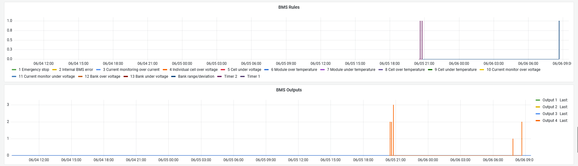
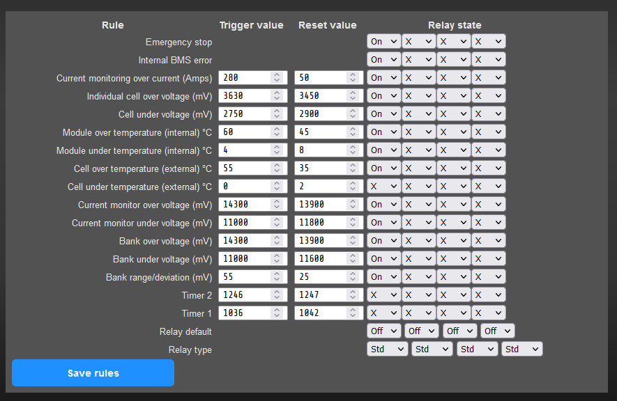
It disconnects the battery once a while (once 1-2 weeks)
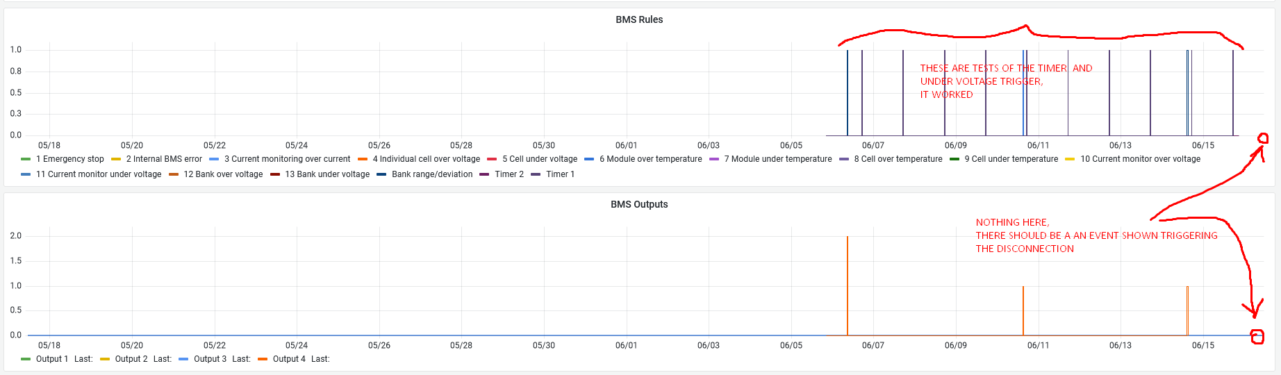
the MQTT functionality does not send status of those disconnections
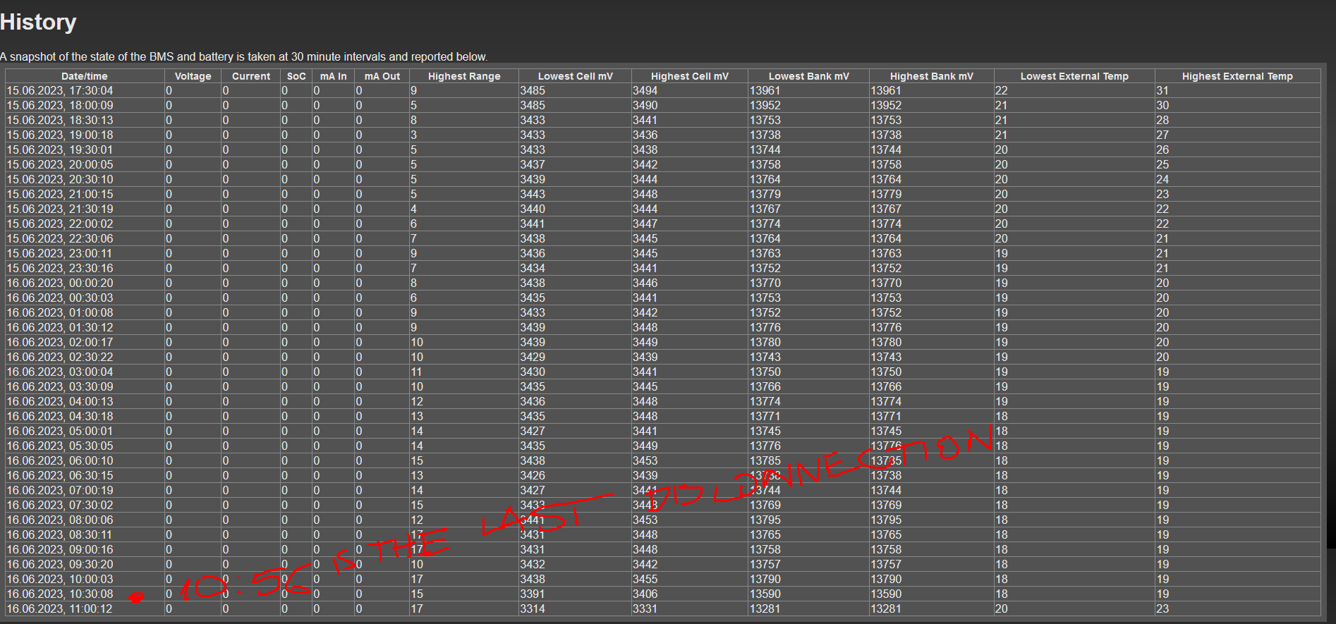
The built in log “history” doesn’t show the triggered events
The effect is I don’t really know what acctually triggers the disconnections
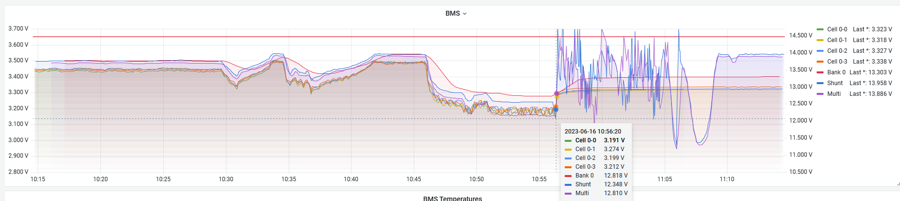
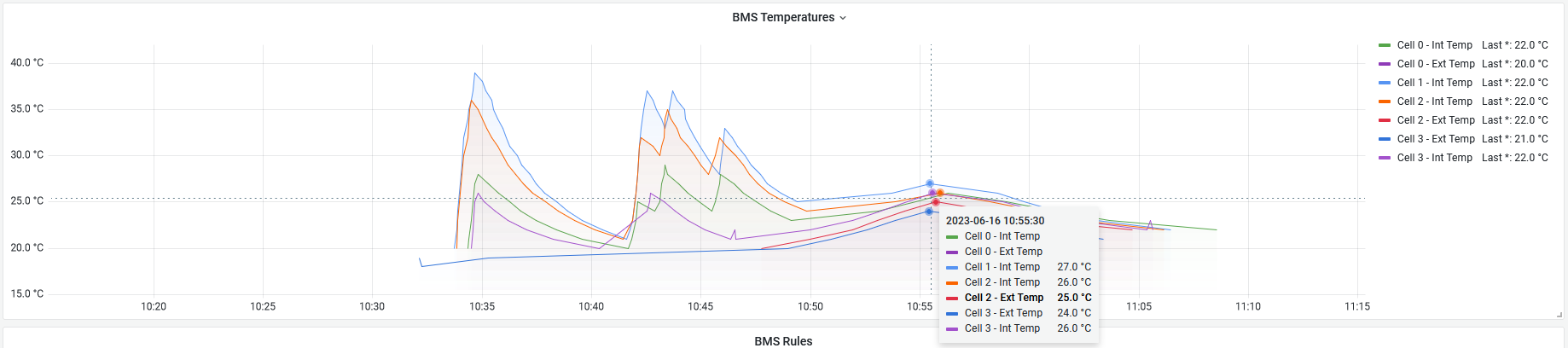
Last disconnection is from today:
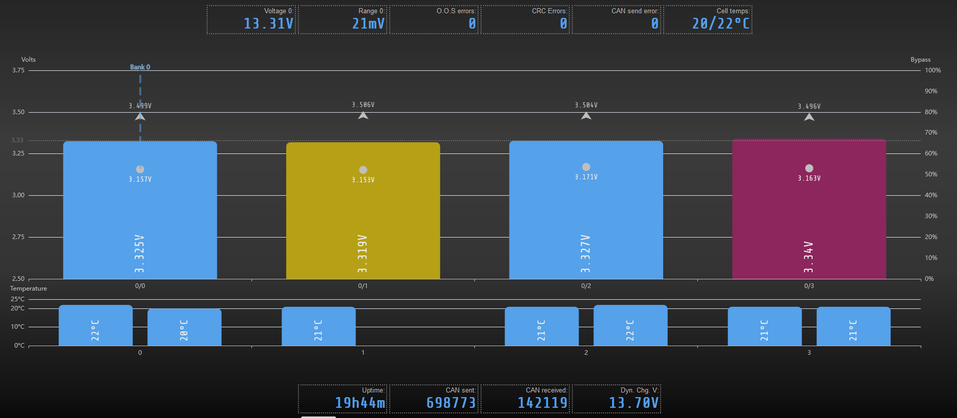
DiyBMS v4.4
4 x Lifepo4 304Ah,
2x Multiplus 1600Va parallel + Venus OS on Raspi 3B+ giant busbars so not voltage drops
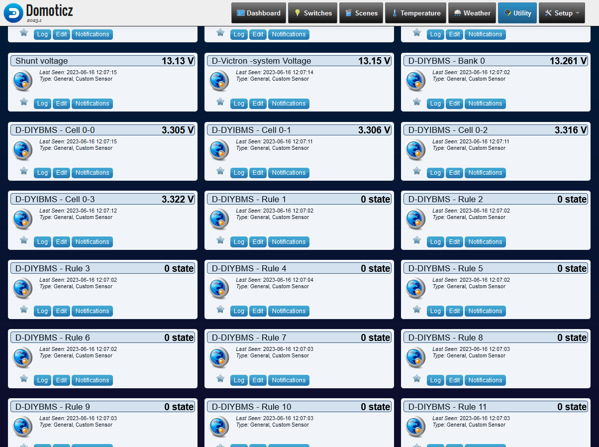
all temperatures, volatges, outputs, events are pushed to graphana using mqtt → Domoticz → InfluxDB → Graphana. The direct Integration for InfluxDB in DIYBMS never worked for me, for a reason I didn’t ever figure out.
temperature probe on Cell 1 is phisicaly disconnected as it caused issues (I wrote about that few weeks ago, since then it doesn’t show the “Low temperature” notification in Venus )
So the question is: How to know what triggered the disconnection ?