I have tried new cables and I still have the RS485 communication problem. Could it be that the ADM2483 is broken?
Stuart: Is there any way to diagnose the Shunt by terminal or any other way?
I have tried new cables and I still have the RS485 communication problem. Could it be that the ADM2483 is broken?
Stuart: Is there any way to diagnose the Shunt by terminal or any other way?
Hi there,
I don’t think I have missed anything, but I thought I would double check here just to make sure. I am currently replacing my Batrium system with DIYBMS. I have a few of the 4.4 cell monitors going on my battery(7 out of 28 needed). I have circa 46KW/Hrs of storage from recycled 18650’s. All packs are close, but not exactly matched. I would like to be able to balance packs before they start top balancing. In batrium this is called “AutoLevel” and it helps to balance out packs that are mismatched. I start the balancing at circa 65% charge, and by the time it reaches the top, they have a chance to balance. Otherwise the small 2a drain per pack is just not enough to drag the high packs down when I am charging at high amps. I don’t think there is anything built in to DIYBMS to level mismatched packs before they get to the bypass top voltage is there?
No unfortunately there isn’t this feature. As you mention, it takes a significant amount of time with larger battery packs/cells - so you are normally better just building the pack in parallel and doing a full charge on that.
Yes I think that could work - if you simply comment out
    // Timer can get to 0
      tftsleep_timer--;
in main.cpp, the screen should be on all the time. If you also remove IncreaseDelayCounter then only the first page would be shown.
Note - the reason the screen isn’t always on, is down to power usage - the screen and LED’s are power hungry, not always ideal in a battery setup.
Possibly, take a look at the USB output/terminal output logs and see whats reported.
Normally, RS485 either works or is doesn’t - it isn’t normally intermittent.
The error is reported when no reply from the current shunt has been received for 45 seconds, or the modules have not reported for over 10 seconds.
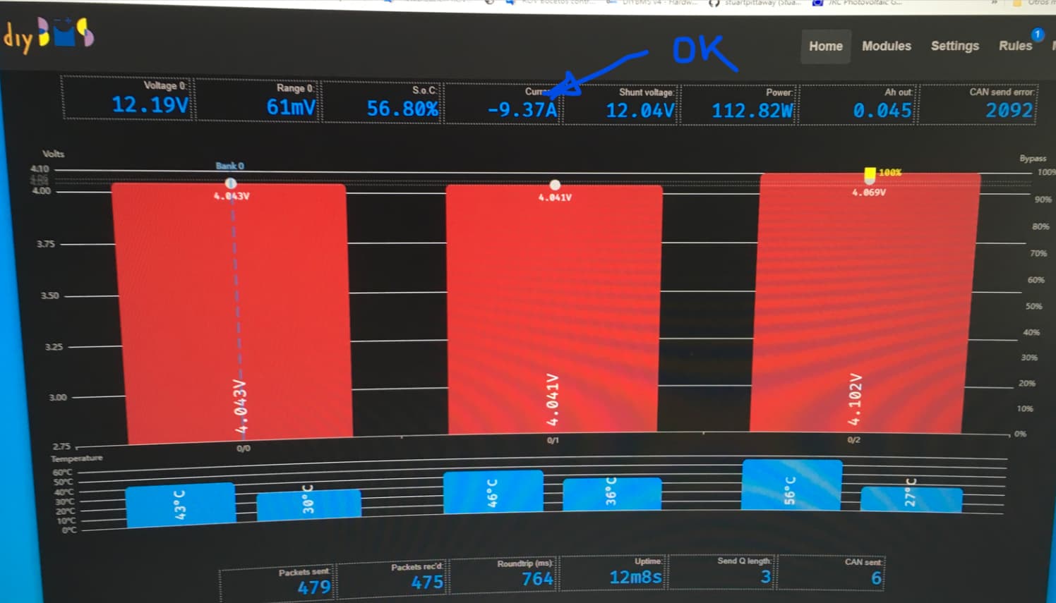
Does the DIYBMS user interface show any current/voltage readings from the shunt?
That doesn’t work too well. My packs are built with “matched” cells and they’re perfectly top-balanced at 3.57V, but there’s >70mV difference between min and max cells when I’m at ~3.3V.
Thus, whatever I’d drain at that level (a whole lot, given the cells’ flat charge curve) I’d just have to put back later – which translates to draining all the other cells. Not a productive use of your energy.
Yeah, I find it quite handy for my situation (LiIon recycled 18650’s), but if my packs were all the same cells of the same age, etc, then yeah, I wouldn’t need much balancing, also when I can’t fully charge my packs (like now in winter in Australia), then I like to start balancing at a lower charge percent. My powerwall is all recycled cells, is probably 4 years old, and likely has a few more years left. My next wall will likely be purchased prismatics, and likely LiFePO4 cells…
Thanks for your reply Stuart.
There is no intermittence, there is simply no data reaching the controller from the shunt. it is as if it were not connected by RS485 to the controller.
The DIYBMS user interface does not show any shunt data.
How can I get data from terminal output/USB output logs?
Ok - so there is no reply from the shunt, hence the timeout you see.
So please, double check the connections/soldering to the shunt and the ADM chip.
Do you also have the 120 Ohm termination resistors enabled?
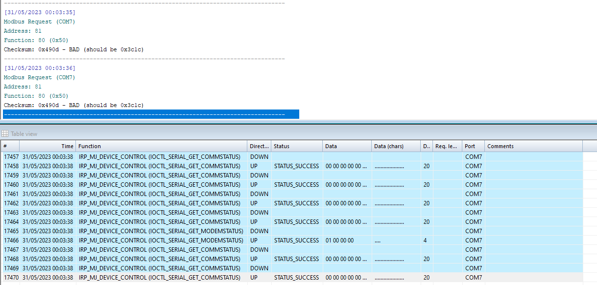
Ok, so the screenshot you sent shows bad CRC error messages.
I’m still suspecting a soldering issue between the qttiny and adm chip, follow the traces for the TX line from the attiny chip.
checked, all traces and solders are correct. As I have ordered things in mouser (ina 229) I have also ordered Attini 1614 and ADM I will replace them to see. Thank you.
I also updated the DIYShunt that I have in the solar system with the UPDI programmer and it updated well, so an error in the Attiny programming is also ruled out.
Could it be a problem with the INA or the LM? I imagine that the LM isn’t because it wouldn’t work, what it seems is that it doesn’t communicate correctly. Any faulty condenser or coil, could be causing the communication error?
The shunt chip appears to be receiving communications from the controller - hence the green flash every 4 seconds as it should. Just no reply getting back to the controller.
It could be an issue on the controller side? Worth checking soldering around the RS485 chip.
i tried 2 diferents controller
Ok, must be a problem with the shunt then. Have you tried setting the ATTINY fuse settings? Wrong clock settings could cause serial port issues.
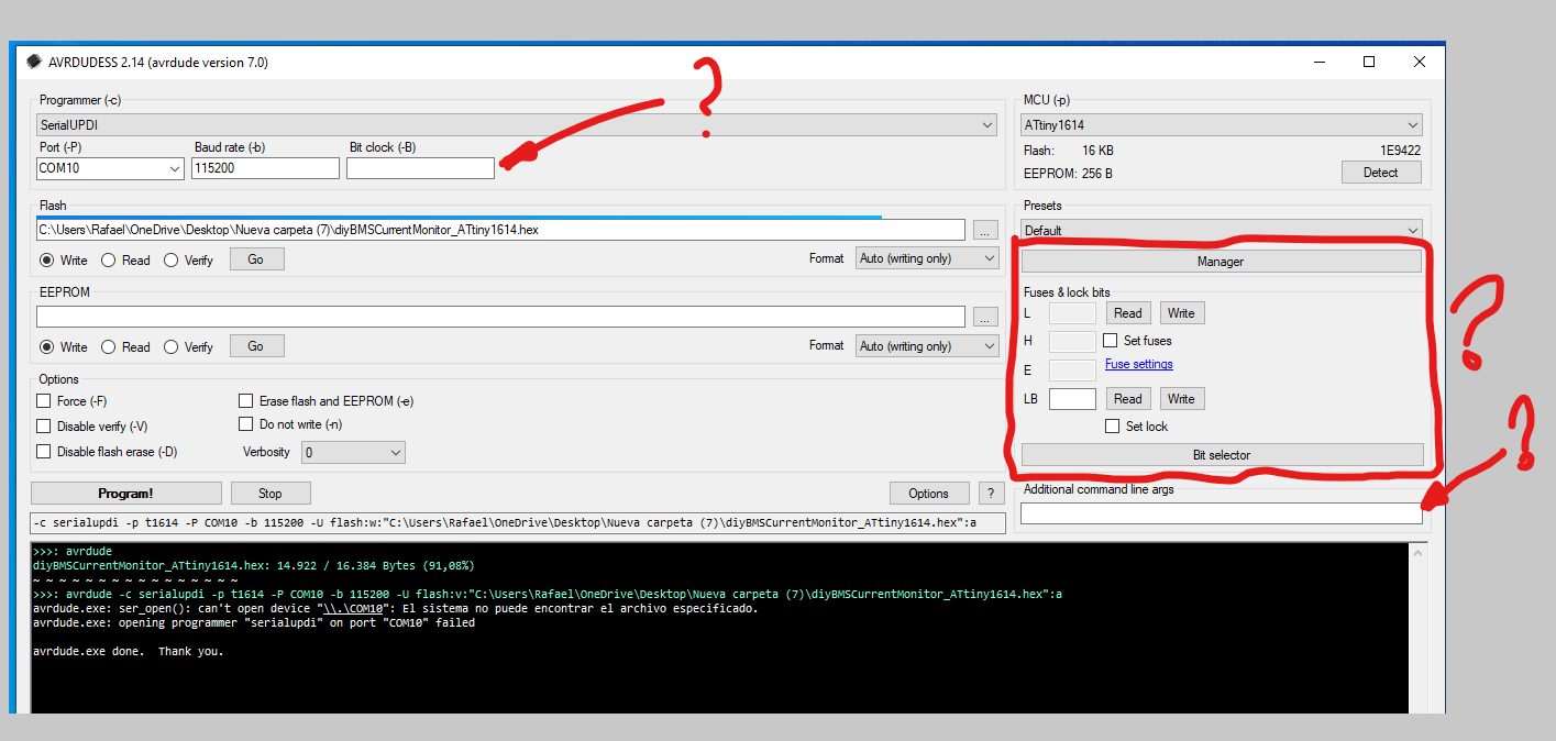
I’m sorry, but I hardly understand this, how could I check or configure the ATTINY fuse Settings ?
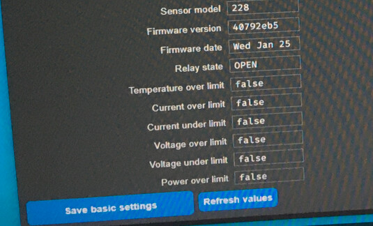
Should I add something else in any of these fields?
I have also tried with a JTag2UPDI made with an arduino (with which I originally programmed the Shunt) and the command
avrdude -v -p attiny1614 -C avrdude.conf -c jtag2updi -b 115200 -P "COM8" -U flash:w:diyBMSCurrentMonitor_ATtiny1614.hex:i

Can the values to adjust the fuse be added to this command?My mistake - the attiny1614 files have the fuses built into the source code HEX file, so no need to put it on the command line.
I have already received the ICs, I have replaced the Attiny and the ADM and I am still the same. It is hard for me to think that it is the controller, because I am testing with two and it is hard for me to think that both have the RS485 communication IC wrong. Could it be that the Ina has broken down? . I ALREADY have the Shunt adon, I have already been able to mount the INA. I’m going to try it on one of the plates. to see what it can be
I have already been able to try to test the Shunt on board, and I have the same RS485 error message. Should I try to replace the SN65? Do you think it could be another problem?
Another question with the Shunt On Board installed, can I also connect an external shunt without having to remove the onboard current shunt/monitor?
Two news, one good and one bad.
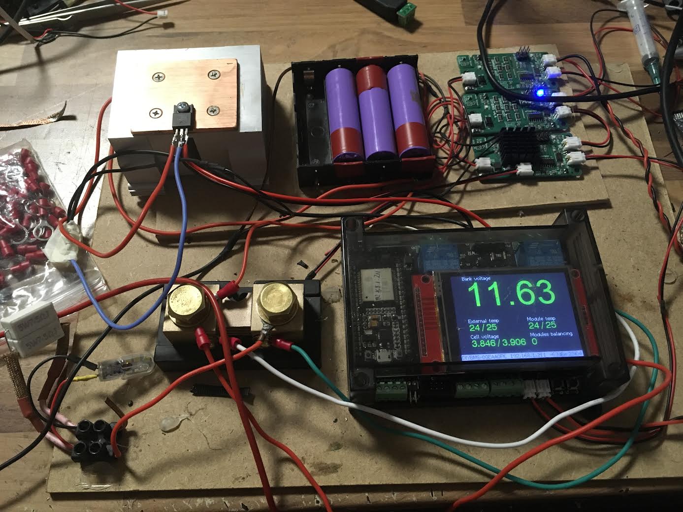
The good first. I have managed to get the DIY Current Monitor to work ( I changed the ATtiny and ADM as I said , even in view of the new information , perhaps it would not have been necessary ) when I tried it with the latest version of the controller fim the error appears communication.
Desperate I began to consider changing more ICs, however I remembered that I had an ESP32 with an old version, specifically this one
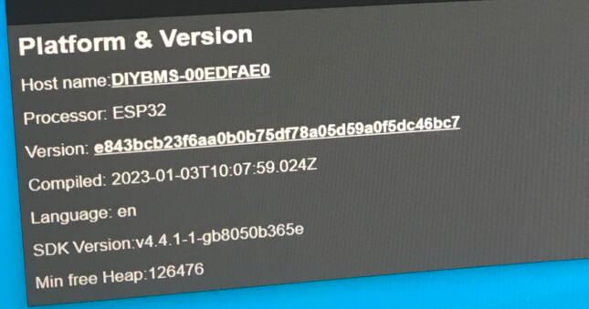
and Voila, the Current monitor came back to life
I leave the firmware version of the Current Monitor.
Now the bad news.
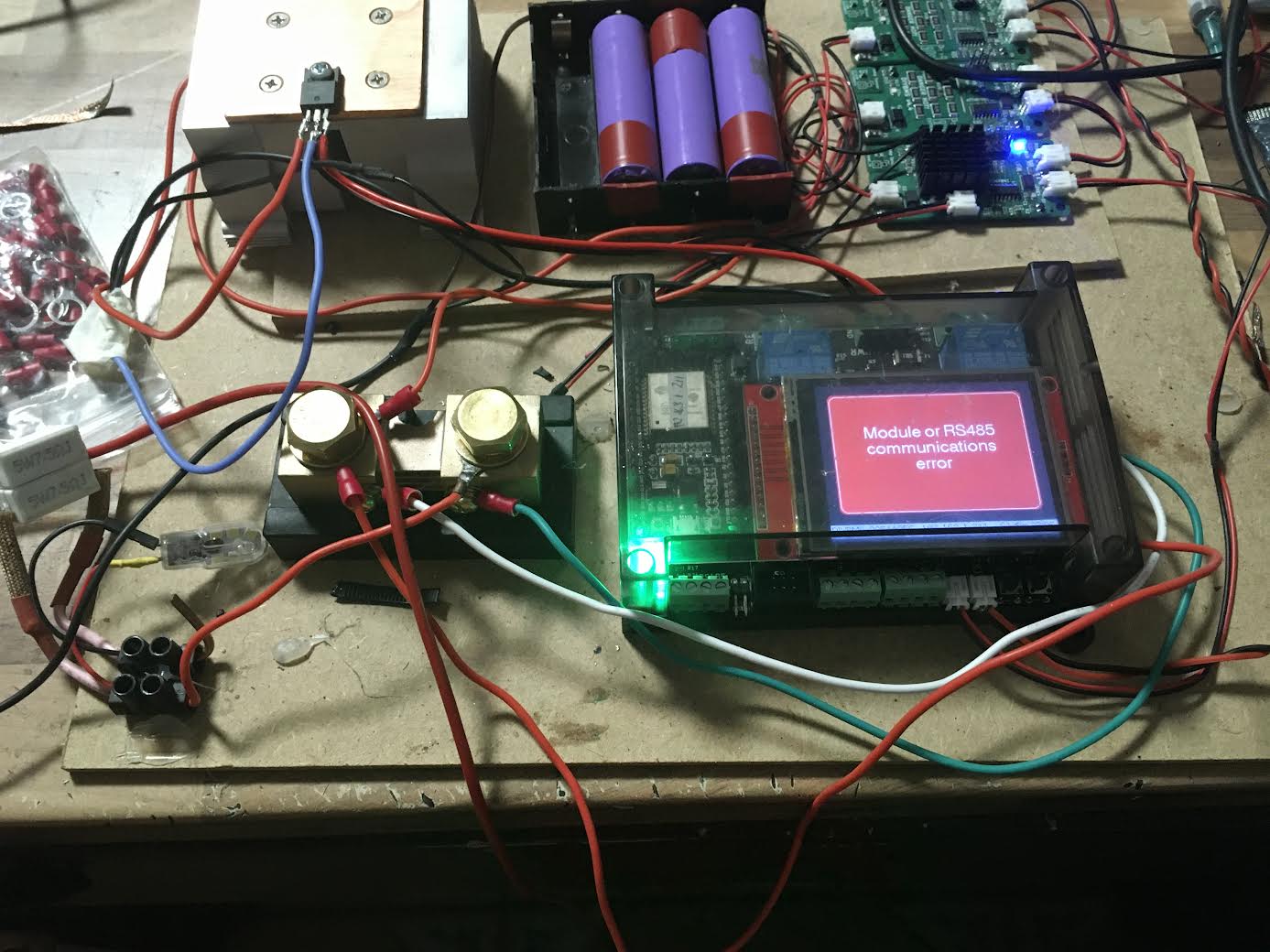
With the latest firmware version of the controller
I leave a screenshot,
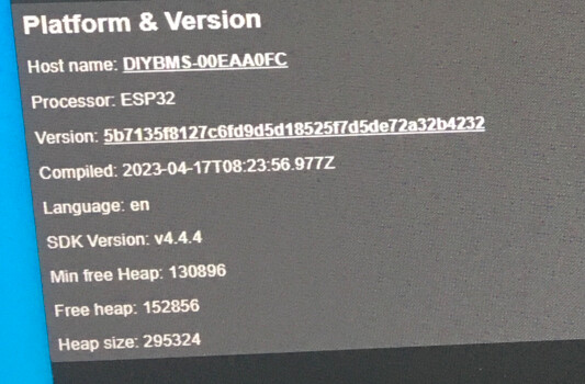
the communication error is reproduced.
I started today to fit the addon current monitoring board and i had only 2 50mV 50A shunts , but i have 30 shunts at 75mV 50A. I was looking through the menu in diy bms and i saw that I can select the shunt mV. I set it to 75mV and it works with one small issue , it stops at 27A charging or discharging. Any idea what to do?
INA 229 on ADCRANGE = 0 has the shunt range up to 160mv and on ADCRANGE = 1 40.96mV
Shunt voltage input range
TA = –40°C to +125°C, ADCRANGE = 0 –163.84 163.84 mV
TA = –40°C to +125°C, ADCRANGE = 1 –40.96 40.96 mV