This is a strange one @philips - however great bug reporting, screenshots and lots of info - thanks.
Is the single relay used to disconnect the battery? How is that connected?
Are you using CAN charge control ?
As the MQTT data is only logged out at a fixed interval, I suspect the error is toggling on/off quickly so the disconnect happens, but isn’t caught by the MQTT interval.
In the next release, I’ve changed the MQTT triggers, so it runs on status change rather than just a fixed interval. You can install this release if you wish to. This may help narrow down the problem.
You may need to capture the serial output of the ESP32 for a long period of time until the error occurs.
Is the single relay used to disconnect the battery? How is that connected?
Relay 1 on the DIYBMS is releasing a 12V which goes to a 12v coil that disconnects a huge 300A Schneider DC breaker.
Are you using CAN charge control ?
DiyBMS is communicating with Venus OS on raspi using 1x Can Hat for Raspi. CAN charge control screenshot are above.
As the MQTT data is only logged out at a fixed interval, I suspect the error is toggling on/off quickly so the disconnect happens, but isn’t caught by the MQTT interval.
OK, this explains alot although I set all the outputs to Std (before I used Pulse) hoping that would help (and it didn’t).
I’ll upload the new release and see, that should help.
How to capture ESP32 serial for a week or two ?
Setup a laptop or spare rasp pi to log the serial output from the ESP32.
On a laptop, I use Putty to capture the output to a file. On Linux/Rasp Pi you can simply redirect the serial output to a file, or use the “screen” tool to do similar.
Hello, maybe someone could point me in the right direction did a stupid mistake I connected the ESP32 Controller4.5 and a 4.4 module with the ISP connection cable while the module was still attached to the battery, sadly there was some smoke the ESP32 module was powered over the USB connector and is dead, I installed a new one and managed so far that the controller is running but the display is black and I can´t program any modules and also the current shunt module (new one) is not showing up so I think there is a dead chip, optical the looking all good but maybe someone can help guess which one it could be to change. THANKS
If you have lost connection to the TFT and the current shunt chip - its possible one of the tracks on the PCB has burnt out - especially if there was smoke. Thats the first thing to check (front and back of board).
Hey Stuart thanks for the fast response was Not clear enough Smoke was only on the Module side, i checked the Board no visible Damage on Booth Sides, also did some Checks With an Multimeter cold Not find an broken Route or dead resistor
Dear all,
Finally, my DIYBMS 4.5 and LiFePo batteries in 16s configuration are running with my DEYE 12K inverter.
Unfortunately, I can only run it in “Dumb mode” as my CAN bus seems not to work as hoped.
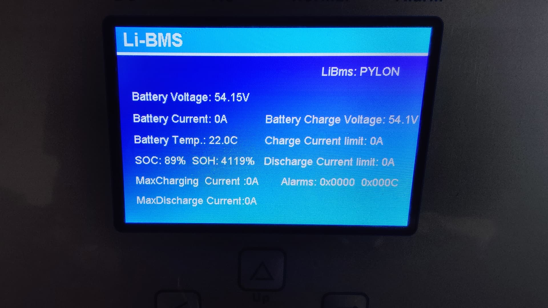
The inverter recognizes that a “Pylontech” system is connected via CAN and both systems are told to use a Pylontech emulation.
Strangely, the DIYBMS controller reports under “tiles” that here are no CAN bus errors and that a couple of thousand/hundreds packages have been sent/received. Looks to me like it works in principle. However, the inverter’s onscreen BMS pages show zero voltage/-75 deg/0% SOC (vs. DYIBMS 54.3 V/21 deg/98% SOC) so as if no information has been received by the inverter from the DIYBMS system.
Any ideas what could test in a next step? I am currently out of ideas…
Any help appreciated!
BTW, the shunt is not yet installed but that shouldn’t affect the general ability to communicate over CAN, correct?
You really should have a current monitor installed first - there is even a warning on the configuration page to that effect. Some values such as SOC absolutely will not be sent unless it’s connected. At a quick glance of the code V and T appear as they they might be reported without a monitor installed but… you’ll still be stuck in “dumb mode” until you install it anyhow, right?
I do agree…however, I fear that there is something wrong irrespective of the shunt?
At least the voltages and temperature(s) should have been transferred, correct?
@stuart I’m going to add an 14S active capacitor balancer to my leaf setup; is there a rule that would disable (i.e. normally short-circuited relay contact disconnecting balancer’s RUN terminals) the balancer when any of diybms module being dumping a cell? otherwise they would counteract each other…
Whay exactly are the relays for in the controller board? I’m planning to use the DiyBMS for an ebike build. Specifically, with a 20s lithium ion setup and a peak battery current of 100 amps.