As in the picture above if I browse to the Storage tab, and do nothing, I see the red bar "Cannot communicate… " after a couple of seconds and the controller restarts. I’ve tried other cards seems consistent? Seems to read the card OK after controller update so it sounds like some history on the card is causing it. Nothing else on the card. I’ve got a spare controller on the bench I can experiment with. The problem report you mention seems slightly different and I was seeing that previously although I’m not sure I tried not pressing mount before?
Hi! If there is anyone that would want to help me make the order online from JLCPCB for the new 4.6 modules. There are a few parts missing from stock, would need help with chosing alternative ones as well as avoiding any other common mistakes. I have a tendency to worry a lot, so would help a ton if someone could help me manage my anxiety when making the choices that need to be made. I can compensate you for your time. Thanks a lot!
The ones I couldn’t read had no PARTUUID. If I recreate the partition table they get one.
So something subtly different on the old cards partition or filesystem.
Tried that with the offending sdcard and it works fine on the bench but still crashes in the battery.
I (150699) diybms-webreq: API call: monitor2
D (151166) diybms: Send addr=90, func=3, len=8
D (151436) diybms: Recv 97 bytes, id=90, cmd=3
I (151466) diybms-webreq: API call: storage
[143223][W][sd_diskio.cpp:186] sdCommand(): token error [13] 0x11
[143224][E][sd_diskio.cpp:621] ff_sd_status(): Check status failed
Recreating the partition table and the filesystem made the old sdcards visible.
Recreated both on the card from the battery and it works fine on the spare controller on the bench: visible and no crashes. Put it back in the battery and it crashed as above. Presumably a physical issue of some sort. I should try swapping the display?
@Andrew_Congdon if you have a bench supply, one idea would be to try using that for a while to power the controller, you’ll be able to compare amps consumed by the controller and pinpoint unexpected peaks or shorts that get the amps over the limit set in the supply (and reboot the thing)
I am just about to start building the DIY Bms for my solar powerwall and i have a question about pylontech emulation. I hope is the right place to ask and not breaking any forum rules.
My inverter (voltacon conversol max gen1) does not have canbus (the manual states it has but it does not, after days of research and phonecalls with voltacon it has been confirmed only rs485 is available )
Option 1: can i use the emulation through the rs485 port of the DIY controller?
Option 2: can i use a Canbus to Rs485 bidirectional converter to connect DIY bms controller CAN to my inverter’s bms port rs485?
having or not having canbus is one thing.
the main issue is what protocol and instructions your voltacon conversol max gen1 inverter uses to communicate with “its” battery.
Pylontech simulation (as victron one) works with h/w that expect these particular instructions.
I’ve never heard of this voltacon you have, so no idea, just pointing out the general concept.
basically Voltacon inverters are just another rebranded subsidiary OEM Voltronic (examples of other Voltronic derived invertrs: MPPSolar range, Axpert, Orient Power).
also this inverter does work (the supplier even sells kits of this inverter with pylontech batteries ) with pylontech batteries plus many more others successfully but through the rs485 port.
Tried an external power supply, no change. Changed power cable, tried power to ESP32 and 5V, no change. Put a monitor on the supply line, stable 5V 22mA with display lit and 18mA in screen saver. No change when controller crashes. Tried changing the display to a dimmer model and it crashes every few seconds without browsing! Must be something on the boards themselves… time to swap them out and try to recreate on the bench.
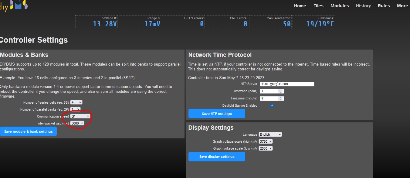
So finally the Atiny 1624 chips arrived at the end of April (ordered on January, where supposed to be on March, than changed to June) , modules are already working.
Definitely there should be a short tutorial/film on how to program those, it took me a while to figure this out.
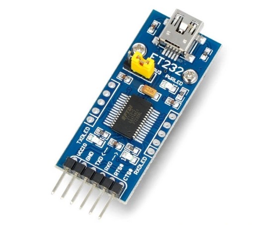
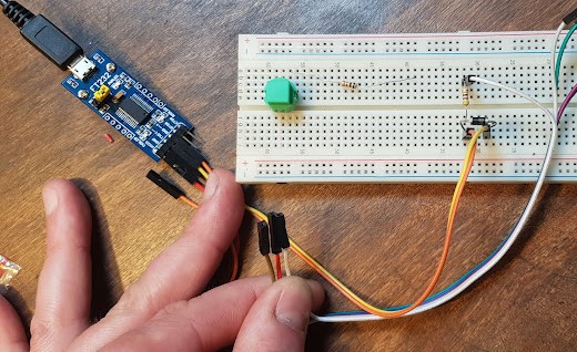
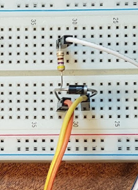
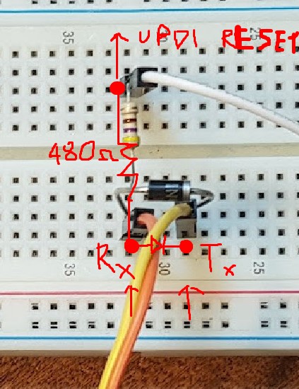
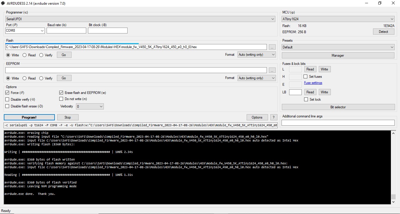
I used to program the Atiny 1624 a FTDI converter with a schottky diodie on RX-TX and a resistor on to “UPDI Reset”, to upload the code I used the AVRDUDESS 2.14 where the FTDI was chosen as “Serial UPDI”. Changing the speed of COM port is not that necessary (few seconds of difference).
Install AVRDUDE (its a command-line software but don’t dive into how to use it, you are not going to do any commands) : Releases · avrdudes/avrdude · GitHub
I also managed to program Atiny1624 using Arduino but it’s way more complicated because you need first to program the Arduino to act as a programmer using dedicated software called Jtag2updi firmware (which also need additional libraries to work) and finally use AVRDUDDES to make the final programming, more here: Turn Your Arduino to a UPDI Programmer - Electronics-Lab.com
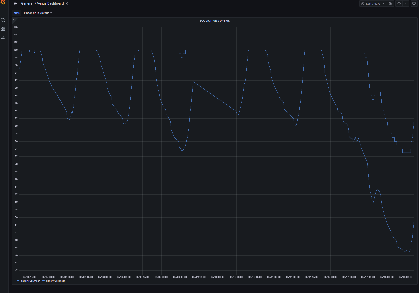
Help with the operation and reading Shunt DYBMS vs Victron BMV 712.
For 10 days I have been away with the installation running and checking it a bit remotely. In this interval the battery has been discharged very little. In the last two months he had identified a deviation in the SOC reading between the two of 10% to which he had not attached importance. Yesterday I decided to do a test to discharge the battery a little more and stop the solar production of the inverter to force the discharge and the increase in deviation between the two readings has caught my attention (above the BMS SOC and below the BMV712 SOC, 73% in DIYBMS and 47% in BMV). Is such a deviation normal? How do you think I could force them to equalize a little more?