DIYBMS v4

Stuart
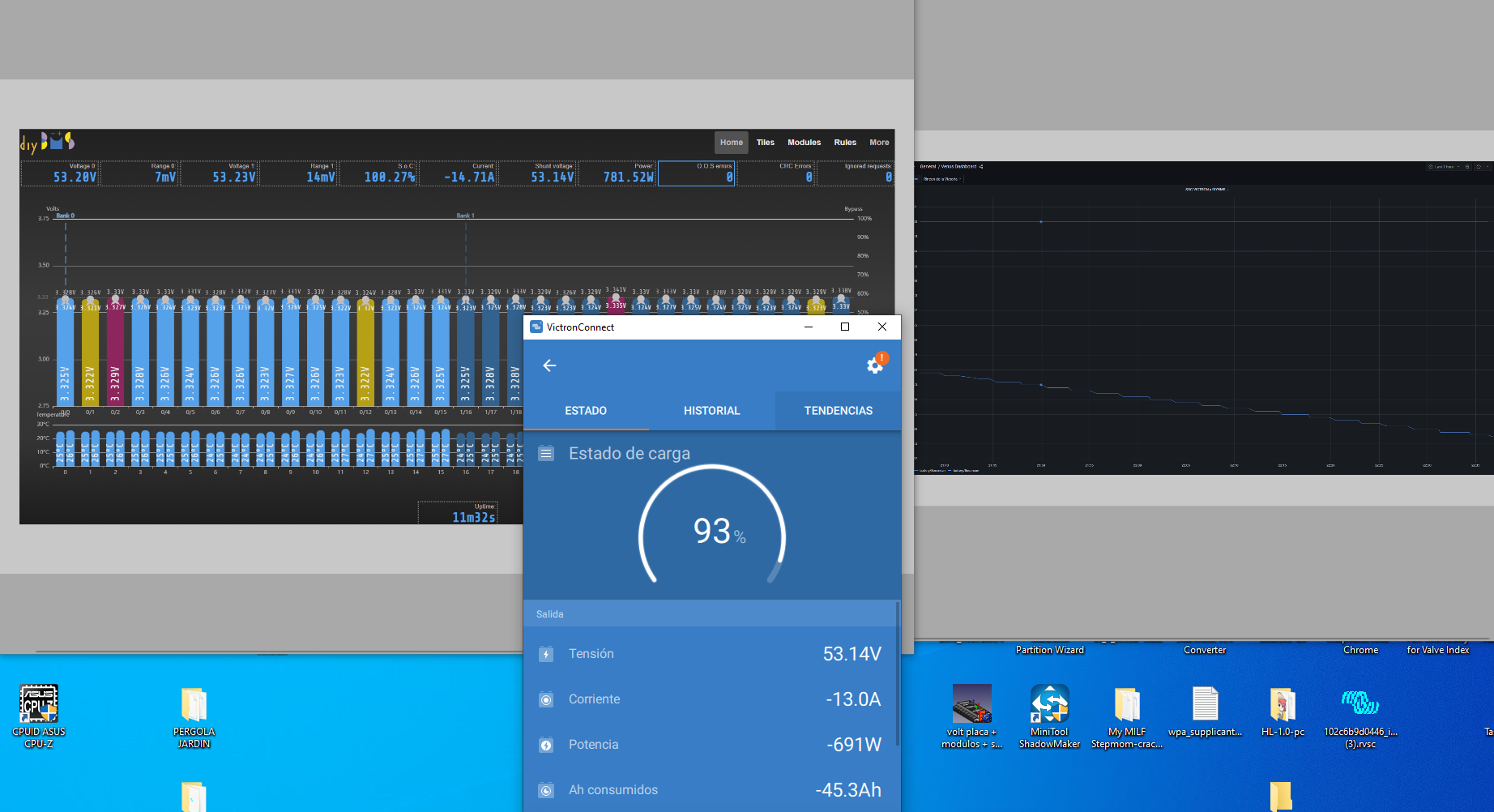
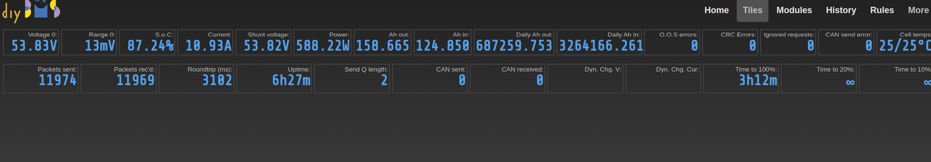
After two weeks with the new firm and an impeccable operation. Today I have seen that the SOC does not start to go down as the battery discharges. As I also have the Victron Shunt I have the two values of the DIYBMS Shunt and the Victron Shunt. What could be happening?

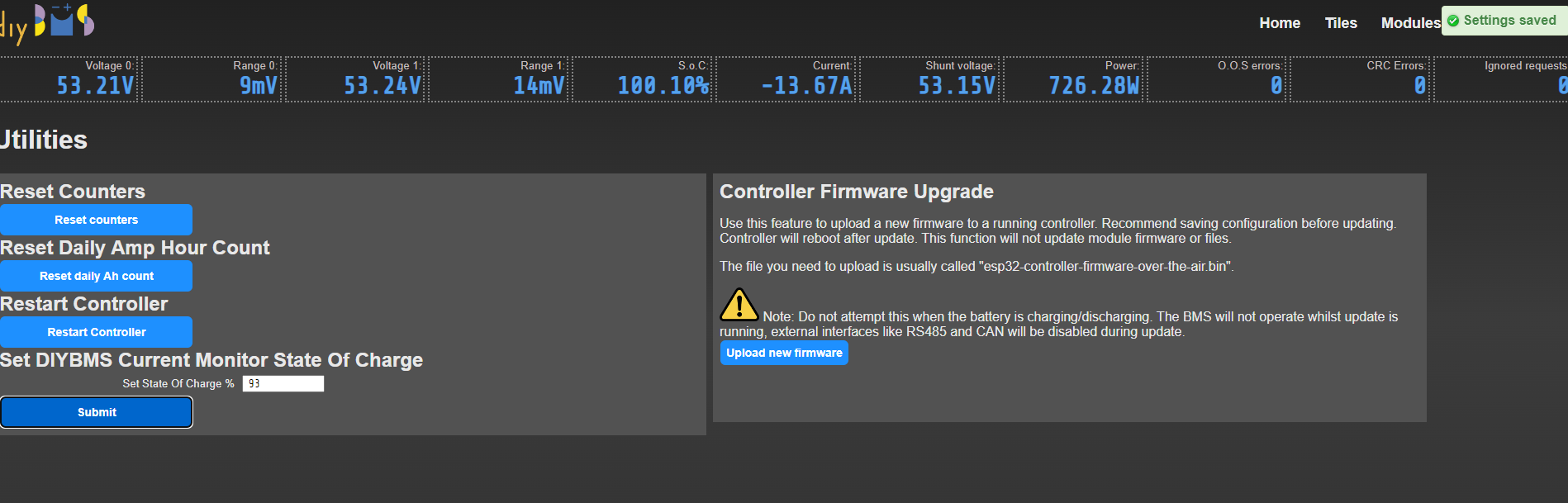
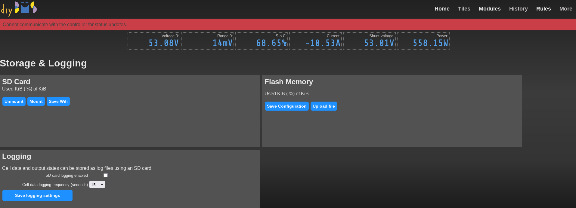
I have also tried with the utility option Set DIYBMS Current Monitor State Of Charge I have tried to change it to 93% but although it responds Settings saved, the shunt value is not modified.

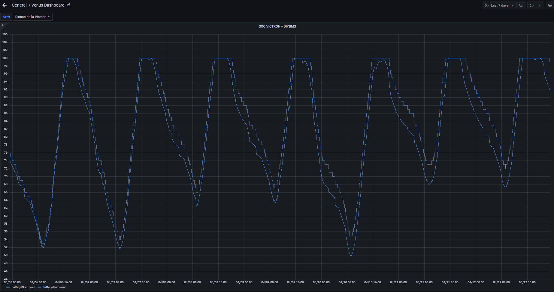
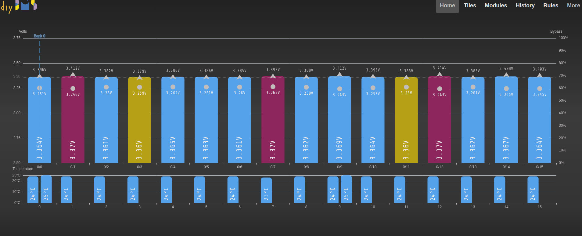
Although now that I look at the data more carefully and observe the evolution of the SOC curve of DIYBMS and the SOC of the BMV of Victron, I appreciate a deviation, I will put the graph for your evaluation. And it no longer seems like a critical situation to me, it is true that there is a deviation that is more pronounced when the download starts and that can be seen as in the last three days it has widened a bit (around a 5% difference)

I built my own release and it created the hex file. But still didnā€™t work. I added this to the cell platformio.ini file

[env:V450_2K]
;DIYBMS V4.50
;Completely different design using ATTINY1624 chip
;MV_PER_ADC is not used by this code, SAMPLEAVERAGING is done in hardware, so set to 1
build_flags=-DMILLIS_USE_TIMERB0=1 -DDIYBMSMODULEVERSION=450 -DMV_PER_ADC=1 -DINT_BCOEFFICIENT=3950 -DEXT_BCOEFFICIENT=3950 -DLOAD_RESISTANCE=3.30 -DDIYBMSBAUD=2400 -DSAMPLEAVERAGING=1
platform = https://github.com/platformio/platform-atmelmegaavr.git
lib_ldf_mode = chain+
lib_compat_mode = strict
board = ATtiny1624
framework = arduino
upload_protocol = jtag2updi
upload_port = COM5
;monitor_port = COM10
;monitor_speed = 115200
board_hardware.updipin = updi
board_build.f_cpu = 5000000L
board_hardware.oscillator = internal
board_hardware.bod = 1.8
board_build.core = megatinycore
board_hardware.eesave = no
;board_hardware.rstpin = updi

When I upload the code to the module using avrdude, the output looks ok and led starts flashing so Iā€™m guesing my DIY updi programmer is working:

avrdude.exe: Version 6.4
             Copyright (c) Brian Dean, http://www.bdmicro.com/
             Copyright (c) Joerg Wunsch

             System wide configuration file is "avrdude.conf"

             Using Port                    : COM3
             Using Programmer              : jtag2updi
             Overriding Baud Rate          : 115200
JTAG ICE mkII sign-on message:
Communications protocol version: 1
M_MCU:
  boot-loader FW version:        1
  firmware version:              6.00
  hardware version:              1
S_MCU:
  boot-loader FW version:        1
  firmware version:              6.00
  hardware version:              1
Serial number:                   00:00:00:00:00:00
Device ID:                       JTAGICE mkII
             AVR Part                      : ATtiny1624
             Chip Erase delay              : 0 us
             PAGEL                         : P00
             BS2                           : P00
             RESET disposition             : dedicated
             RETRY pulse                   : SCK
             serial program mode           : yes
             parallel program mode         : yes
             Timeout                       : 0
             StabDelay                     : 0
             CmdexeDelay                   : 0
             SyncLoops                     : 0
             ByteDelay                     : 0
             PollIndex                     : 0
             PollValue                     : 0x00
             Memory Detail                 :

                                      Block Poll               Page                       Polled
               Memory Type Mode Delay Size  Indx Paged  Size   Size #Pages MinW  MaxW   ReadBack
               ----------- ---- ----- ----- ---- ------ ------ ---- ------ ----- ----- ---------
               signature      0     0     0    0 no          3    1      0     0     0 0x00 0x00
               prodsig        0     0     0    0 no         61   61      0     0     0 0x00 0x00
               fuses          0     0     0    0 no          9    1      0     0     0 0x00 0x00
               fuse0          0     0     0    0 no          1    1      0     0     0 0x00 0x00
               fuse1          0     0     0    0 no          1    1      0     0     0 0x00 0x00
               fuse2          0     0     0    0 no          1    1      0     0     0 0x00 0x00
               fuse4          0     0     0    0 no          1    1      0     0     0 0x00 0x00
               fuse5          0     0     0    0 no          1    1      0     0     0 0x00 0x00
               fuse6          0     0     0    0 no          1    1      0     0     0 0x00 0x00
               fuse7          0     0     0    0 no          1    1      0     0     0 0x00 0x00
               fuse8          0     0     0    0 no          1    1      0     0     0 0x00 0x00
               lock           0     0     0    0 no          1    1      0     0     0 0x00 0x00
               data           0     0     0    0 no          0    1      0     0     0 0x00 0x00
               usersig        0     0     0    0 no         32   32      0     0     0 0x00 0x00
               flash          0     0     0    0 no      16384   64      0     0     0 0x00 0x00
               eeprom         0     0     0    0 no        256   32      0     0     0 0x00 0x00

             Programmer Type : JTAGMKII_PDI
             Description     : JTAGv2 to UPDI bridge
             M_MCU hardware version: 1
             M_MCU firmware version: 6.00
             S_MCU hardware version: 1
             S_MCU firmware version: 6.00
             Serial number:          00:00:00:00:00:00
             Vtarget         : 5.0 V

avrdude.exe: jtagmkII_initialize(): Cannot locate "flash" and "boot" memories in description
avrdude.exe: AVR device initialized and ready to accept instructions

Reading | ################################################## | 100% 0.17s

avrdude.exe: Device signature = 0x1e942a (probably t1624)
avrdude.exe: NOTE: Programmer supports page erase for Xmega devices.
             Each page will be erased before programming it, but no chip erase is performed.
             To disable page erases, specify the -D option; for a chip-erase, use the -e option.
avrdude.exe: reading input file "module_fw_V450_2K_ATtiny1624_450_e0_h0_l0.hex"
avrdude.exe: writing flash (8356 bytes):

Writing | ################################################## | 100% 3.41s

avrdude.exe: 8356 bytes of flash written
avrdude.exe: verifying flash memory against module_fw_V450_2K_ATtiny1624_450_e0_h0_l0.hex:
avrdude.exe: load data flash data from input file module_fw_V450_2K_ATtiny1624_450_e0_h0_l0.hex:
avrdude.exe: input file module_fw_V450_2K_ATtiny1624_450_e0_h0_l0.hex contains 8356 bytes
avrdude.exe: reading on-chip flash data:

Reading | ################################################## | 100% 2.38s

avrdude.exe: verifying ...
avrdude.exe: 8356 bytes of flash verified

avrdude.exe done.  Thank you.

is this the external shunt? what firmware are you using for this?
i had no problems with CurrentShunt [Release-2023-01-25-12-26]

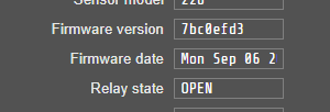
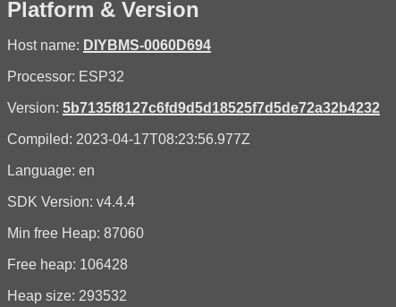
Yes is the external Shunt. The version release is
Compiled_Firmware_2023-03-29-08-24.zip

It really doesnā€™t matter too much, but I tried to use the option to manually change the SOC and it didnā€™t let me, maybe I should update the Shunt Firmware, it is true that it has the first version that I installed, a year or a year ago and medium more or less
image

Is it possible to have dynamic discharge as well with the new controller canbus? My cells seem to go out of whack at the bottom end rather than the top so slowing the rate of discharge should help

Not presently, but open a GitHub issue for this and we can put it on the list.

Stuart, I order the lastest V4.5 module with JLCPCB. They notice an inversion with the D2 and ask for confirmation.


Could you confirm it ?

they often place it wrong

Correct.

compiled latest code for ESP32, on latest VSC/PlatformIO et al in win10 64bit (ie. what Iā€™m always using).
I have to compile as I modify/add bits in influxdb.cpp to monitor some more things on it
two Qs:

  1. why do I get a couple of warnings:

In file included from src/tft.cpp:35:
.pio/libdeps/esp32-devkitc/TFT_eSPI/TFT_eSPI.h:970:8: warning: #warning >>>>------>> TOUCH_CS pin not defined, TFCompiling .pio\build\esp32-devkitc\src\webserver.cpp.o
T_eSPI touch functions will not be available! [-Wcpp]
#warning >>>>------>> TOUCH_CS pin not defineCompiling .pio\build\esp32-devkitc\src\webserver_helper_funcs.cpp.o
d, TFT_eSPI touch functions will not be available!
^~~~~~~
fwiw, tft screen and touch work fineā€¦

  1. can I compile code to a .bin file for OTA installation? if so, how?

  2. I have 1.9F modules with last springā€™s code working fine, do I have any reason to update them as well?
    Hope not as updating the current monitor (and remembering how I did it last year) will be hard enough for today!

cheers

V.

PS. needless to say that Iā€™ve updated whatā€™s updatable, and rebooted VSC a few times for good measureā€¦

Ignore the touch-cs warning I get those as well!

If you use the generate filesystem image option in platformio, then take a look in the .pio folder, you should see a file suitable for OTA upload, it will be about 1.5M in size.

1 Like

I got my diy bms today , along with addon shunt board , V4.5 modules , chapulinoā€™s board , ina229 , attiny and so on.
Now after testing is working great butt ā€¦
Is it possible to conect multiple controlers in a daisy chain configuration , like pylontech. 1 master and slaves?
The reason for asking is that i have 13 lifepo4 packs , 16S 100Ah and i have no ideea how to proceed further. I do not want to put all cells in paralel for the weight reason but also for the redundant function it provides , if one pack goes , the 12 remaining packs are still suplying energy to the inverter.
If is posible to make the controlers comunicate with one another like pylontech , or a separate device/controler that comunicates with all modules present via can bus or serial , sums the info up and send it to the inverter via CAN BUS.
The other way arround this is to fit 2 controlers , one controler with 7 packs and the other with 6 packs and if one pack goes , the whole 7 packs are shut down but i do not like this aproach.

A single controller can run multiple banks. Just connect cell monitors to each cell in a daisy chain and then select 2 banks in the settings

Hi all, just in case. Does anyone have extra cell boards v4.21 ? I have 3, so if I could get 1 or 5 more, it would be great (so I can test some LifePo cells for now, before I order the new boards) Ideally if location is between Belgium and The Netherlands - Thanks

but the controller can run up to 128 modules. Doing the math that will suffice to 8 16S banks but i have 13 16S banks.
Also loading 128 modules on the web interface would be a huge demand for the ESP I suppose.
I will try but the web interface will be very cluttered.

Thatā€™s a lot of banks! Multiple controllers makes sense.

I know , daisy chaining controllers or aggregating data from multiple controllers would be nice. Since the controller has can bus , I would like to use that feature with my inverters , but since daisy chain is impossible at the moment , I will use them without. But my PV setup is the perfect setup for testing new code for data aggregation , Pylontech like comms. In the end my setup would comprise of 20 16S 100Ah packs , 20 controllers and 320 cell monitoring boards.
Today arrived 25 controllers , 500 V4.5 boards , 25 shunt addon boards , 25 chapulino`s board layout.
I would be more than happy to test some code regarding data aggregation.

I recently lost the SOC info for one of my batteries on the Home tab.
Now Iā€™ve lost all the status infoā€¦ is this a recent feature?
Can I get it back?

Itā€™s still there in the Tiles tab:

Go to the tiles tab and click on the information you want on the home page.

Continuing the discussion from DIYBMS v4:

Very nice thankyou.
Sadly controller still falls over whenever I browse Storage.


version

Same on older version on 2nd battery. Config files are there as the OTA update was successful :grinning: