Still no changes…
We are at the end now and have absolutely no idea what to do.
Changed modules again
Tried 4 different power cables
Changed batteries…
Still no changes…
We are at the end now and have absolutely no idea what to do.
Changed modules again
Tried 4 different power cables
Changed batteries…
Attention Update:
The Problem has been shifted:
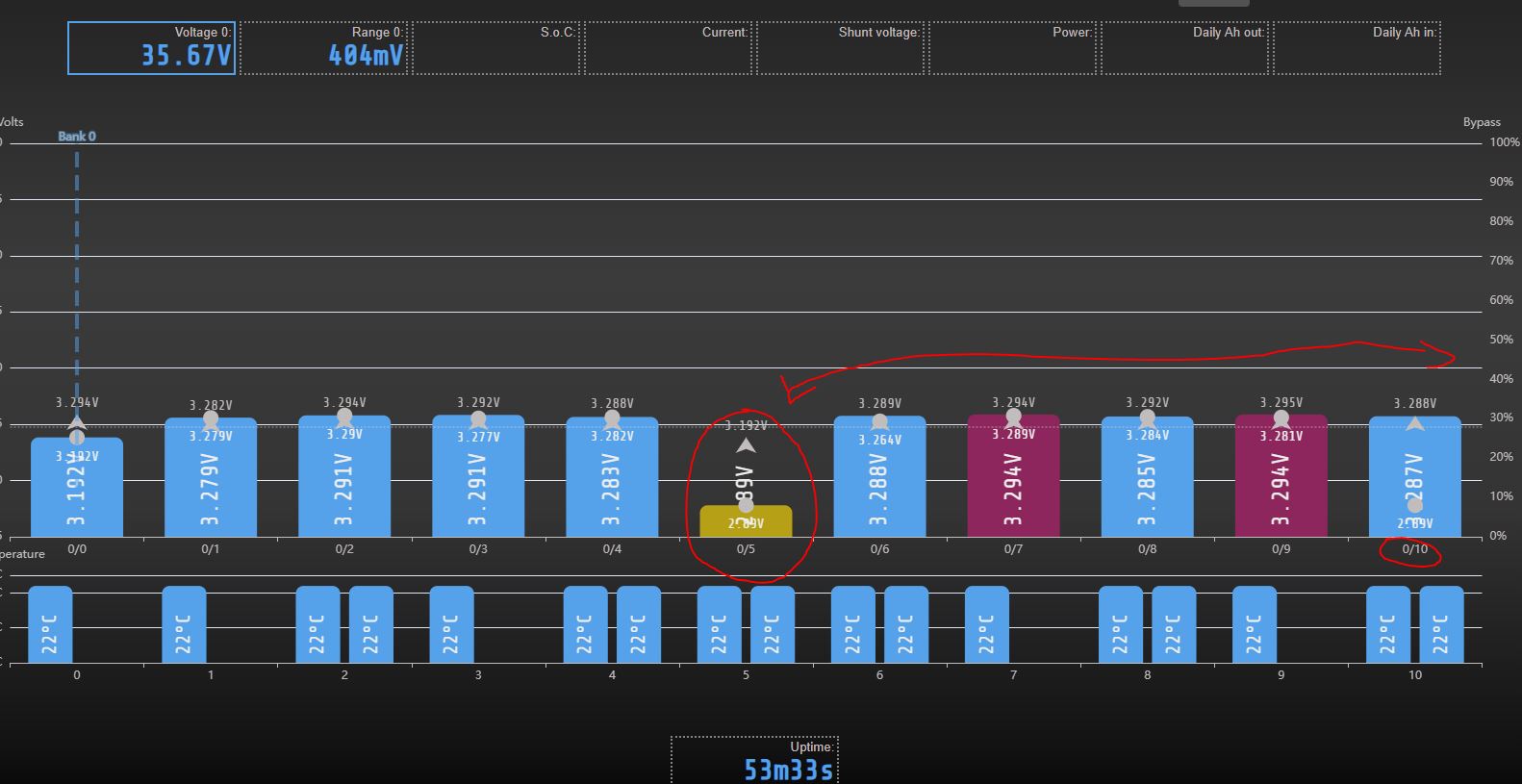
All modules from 16 → 11 (5 modules are now dismantled from the pack) - number 11 was the one that produced that strange voltage I reported before.
Now as you can see in the screenshot, the “wrong” measurement shifted to cell number “6”.
So I´m more and more convinced that we´re talking about a software issue and not a hardware problem. Or maybe a communication problem. I don´t know…
And another update to it:
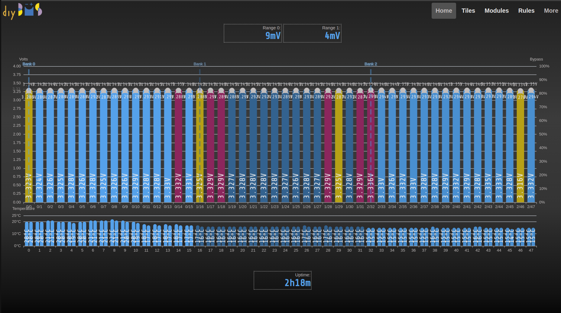
If we start to unattach the modules from top number downwards the problem with the wrong displayed voltage is shifting WITH the modules down until we reach number “0” (1st module/cell).
This is for sure a software issue / bug.
Karl,
When i first built my v4.4 modules i accidentally left off D1 (the voltage reference) AZ432ANTR-E1.
They exhibited the exact same erratic symptoms.
When i say I left off … it was really JLCPCB didn’t have them (nor attiny) - I added the tiny but forgot the voltage ref.
Also make sure you reload your browser - i have on occasions had trouble doing updates to the controller/modules until i reloaded my browser - no error message … just doesn’t work - i haven’t debugged why but believe assume stale cookie.
YMMV
Mick
If it is, it’s the first time it’s been reported in over 5 years! Either way, I’m happy to fix and bugs when found.
I’d be surprised if it were a code issue though. The modules are electrically isolated from each other. They are in effect autonomous, they have their own CPU etc.
All the controller does is ask each module for it’s voltage readings.
In the 2 years I have had this system running, there have been two times that one of the modules has started to go bad, I replaced the D1 and so far. Carlos, from what you describe, it sounds to me like a hardware problem, some component of some modules or of the controller has degraded, it is not frequent, but it can happen
I also recommend that you carefully review the communications (even reviewing the RX TX soldering in each and every one of the modules) and of course the quality of the communication cables
the wait is over , on friday i will receive 57 attiny 1624 purchased directly from Microchip Tecnology . I am looking forward to receive them and test my prototype of 16 modules
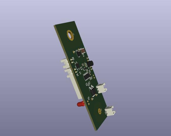
Hello, i wanted on this: https://cz.mouser.com/ProductDetail/Microchip-Technology-Atmel/ATTINY1624-SSF?qs=vmHwEFxEFR9LqbpowBv46Q%3D%3D to solder on my variant 4.5 board directly mounted on cells.
AZ432ANTR have an alternative, i have many LM385-1.2 : LM385-1.2 pdf, LM385-1.2 Description, LM385-1.2 Datasheet, LM385-1.2 view ::: ALLDATASHEET :::
do you want to flash the 10k firmware?
Yes, I want to try the higher speeds
In my previous system for 4.4 modules I can only put speed of 5K
my 16 module board communicates at 10k with 4.5 modules like lightning
can you send me the jlcpcb files and maybe the data for the 3d printed case?
thanks
I attach Feecad and Easyeda files in case you want to make any changes
board for v4.5 v3.zip (118 KB)
easyeda freecad stl.zip (2.5 MB)
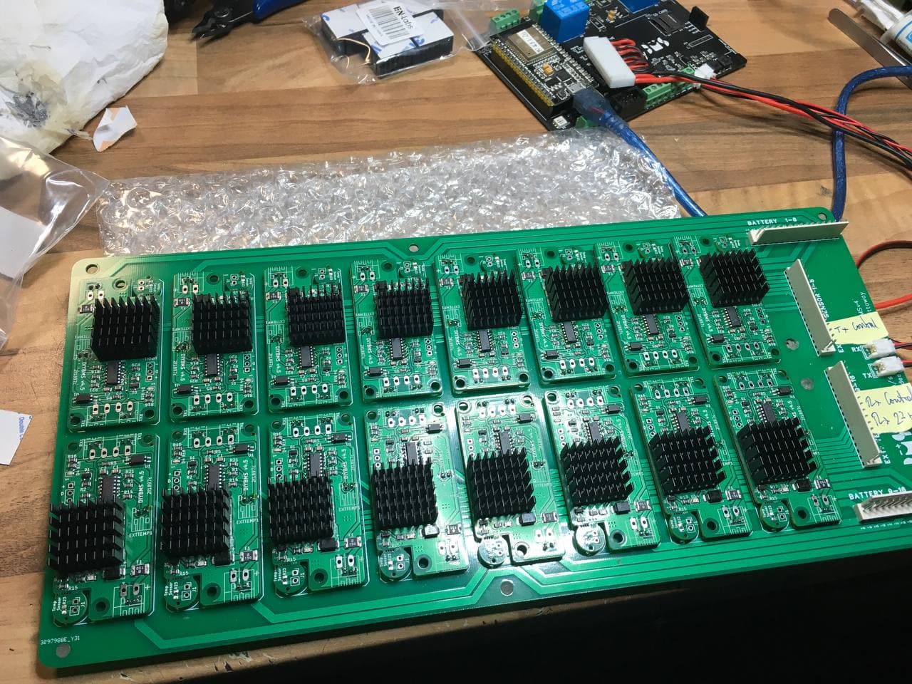
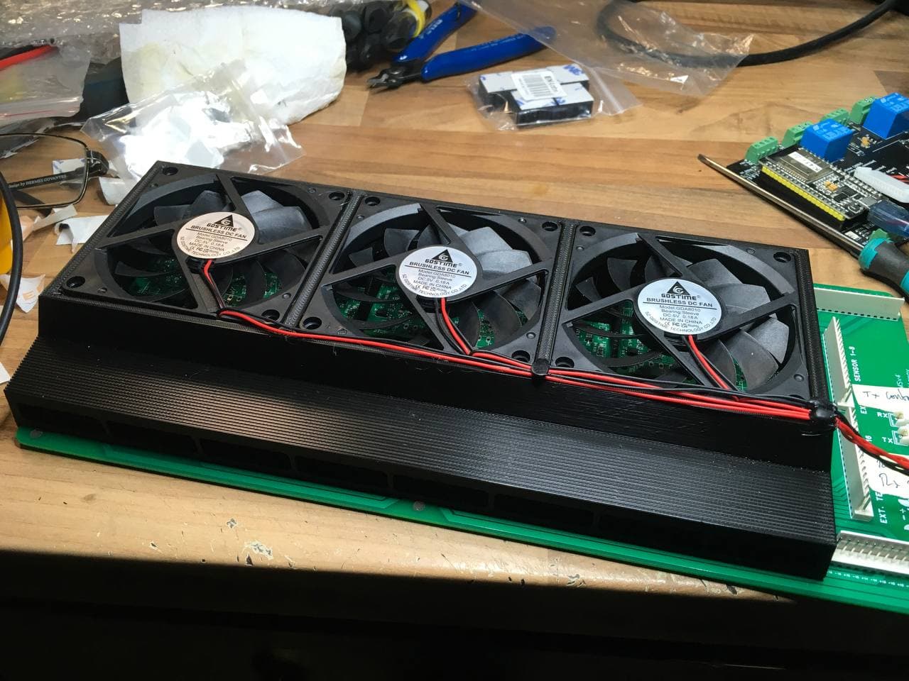
what thermal glue have you used for the heatsinks? and does it still require the fans?
I have not used thermal glue, only the adhesive from the heatsinks themselves. I check that this 3m adhesive does not conduct electricity and therefore does not generate shorts, I will be able to provide you with the Aliexpress purchase link.
Regarding the second question, the heatsinks by themselves can be enough in a battery that unbalances little, but if you have to balance for a long time, the fans combined with the heatsinks allow in the tests I did at the time , maintain a discharge of more than 3 minutes continuously.
In the meanwhile we´ve been able to “fix” the issue.
Several modules died. Why I can´t tell you guys… But at the moment 1 bank is working as it should.
I think it could be that some welderings at the e.g. power cables or something in that direction wasn´t made good from my side.
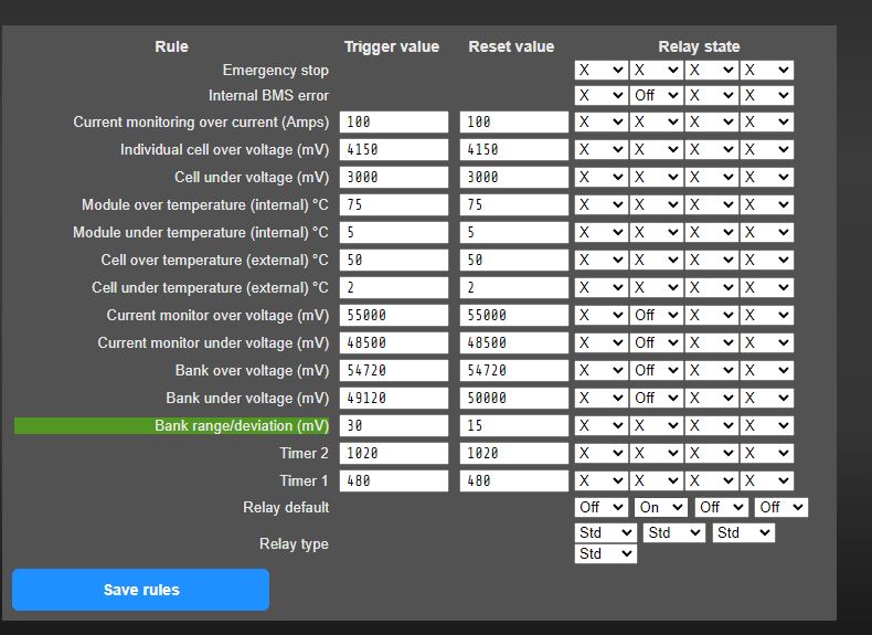
Now I´m struggling with the settings for the 16s Lifepo4 is someone willing to share his settings or comment and overview mine?
At the moment the relais was turning “on” and “off” very often. To fix that issue I pushed the Current monitor OV / UV up to the “mostly” same values of the Bank. Is that correct?
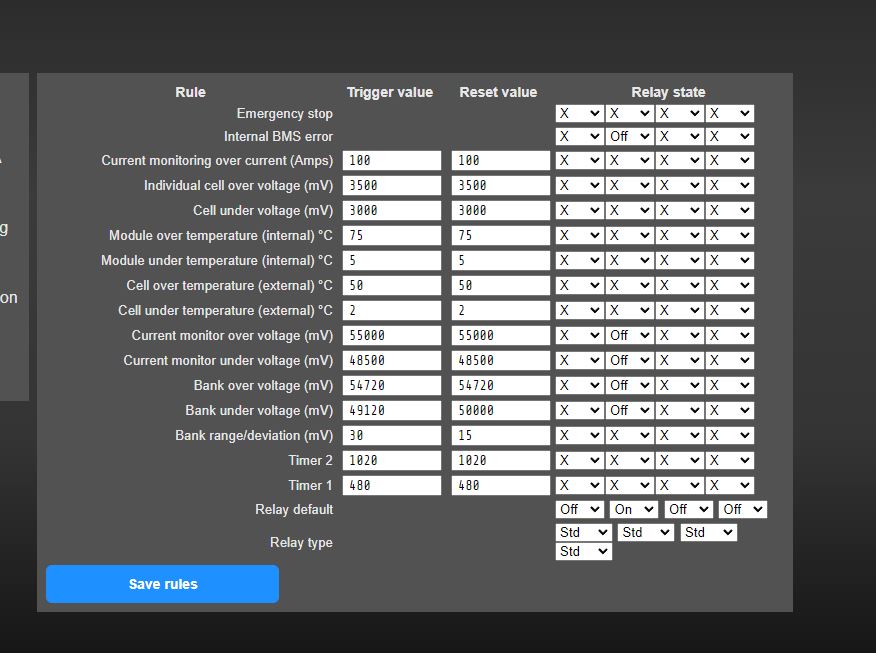
If you are driving a relay/circuit breaker from the controller when those error conditions occur, set the voltages to be real “error” values.
For example, if you normally charge LFP to 3.45V (55200mV), set the trigger values to a higher value like 56800 - those are still “safe” voltages for LFP at 3.55V.
The rules should be considered “error” states, if they are triggered, something critical has happened.
I also recommend setting the “individual cell over voltage” as that is probably the most important thing to control - a single cell going over maximum (perhaps set that to 3600mV).
Thanks stuart I think that makes sense.
I also upload again the “final” settings for the Rules for the next one looking for an example.
Thx
The “cell over voltage” rules doesn’t actually trigger a relay.
I would also not recommend having the relay always “on” - it will draw a lot of power, get hot and fail quickly.
Perhaps consider inverting the On/Off status, and using the Normally Closed contacts instead (so the relay triggers on error).
Ideally, use the relay to drive a “circuit breaker shunt trip” to disconnect the battery DC supply.
set the cell over voltage to 3600 and undervoltage to 2700
and the second relay state both at off
bank overvoltage at 57600 and bank undervoltage to 44000
same for the current monitor
if possible use the relay 3 or 4 for always on and a dc contactor for 48v in normal open configuration
so when the diy bms fails or loose power it will disconnect your battery
the ev200adana is a good one but dont use it without precharge the inverter or it will die soon
also consider to use the canbus dynamic charge voltage limit if you have a canbus inverter
this is a very usefull feature