@stuart @Smurfix
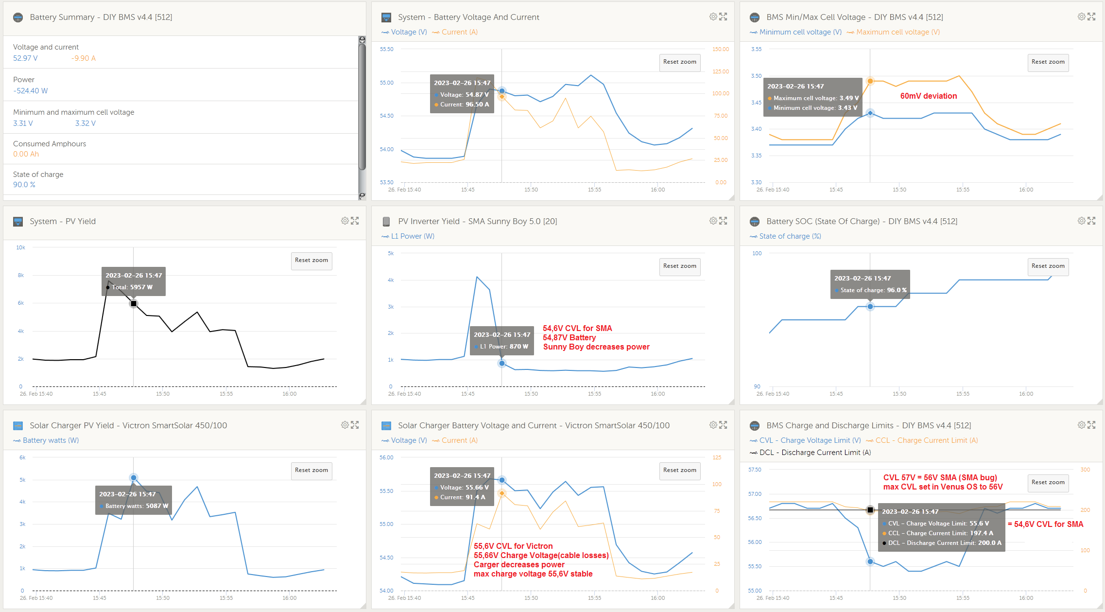
the dynamic charging algorithm is working very well
i have a offgrid system with sma sunny island, sunny boy and victron charge controller
here some graphs from the victron vrm
@stuart @Smurfix
the dynamic charging algorithm is working very well
i have a offgrid system with sma sunny island, sunny boy and victron charge controller
here some graphs from the victron vrm
Glad to be of service. My battery is quite happy about it too.
Stuart, I have been using the diyBMSv400 for over an year and suddenly one module started behaving strangely. It kept bypassing till the battery was fully drained.
I removed the same from the pack and saw the voltage was being read incorrectly 4.4V causing it to bypass.
The voltage divider part is working- I added a resistor in parallel to the lower part and the voltage is dipping as expected. The upper half of the voltage divider was not showing any change with the addition of the parallel resistor.
The reference diode is also working. I ran it off a DC power supply and it’s holding steady at 2V.
My suspicions are the following -
AREF pin could be faulty
PA7/ ENABLE pin could be faulty
Have you faced any similar issues
Could you please let me know the debugging steps.
My pack is a 13s 5p, Controller is based on ESP8266.
Really appreciate and respect your valuable contribution to the Community.
Hi @Ashin_John. I’ve not seen any reports of hardware failure like you describe - it could be a number of things such as you mention. Might be worth checking for foreign objects on the board, bad solder joint?
I did see similar behaviour once when the ATTINY lost its flash memory configuration - so check that first in the web interface (check the calibration value isn’t zero). Additionally, it might be worth re-flashing all the cell modules using a newer version of the module code, to see if that helps.
Hello
It might be the wrong place here to ask - sorry for that.
I’m wondering if the DIYbms is ‘just’ a balancer or if the main (charge - discharge) current is switched off in case of reaching e.g. ‘Cell Discharging Cut-off-V’
I looked through the schematics, but on controller board I only see 2 solid state relais AQY282SX.
AQY282SX is for 500mA, so I think they are not for this purpose.
Or do I have to use an external relais?
Or, the most likely, I did not understand everything in the right way.
Please give me a short advice.
Thank you!
Diybms is designed to control external chargers over CANBUS (like Victron or pylontech).
It can also use it’s relays to drive other safety devices like contactors or bistable relays to protect battery packs.
This is similar to the batrium range of products.
That’s the missing link! Thank you!
Well, you still should have an external relais. This is essential for safety. You do not want to risk your system to go belly-up due to some random misconfiguration.
However, this relais should only trip if the rest of the system misbehaves in some fundamental way – and blatantly ignores the voltages or currents which the BMS tells it are acceptable. High-energy batteries are not “battery full? well, turn off the charge path” devices.
In particular, when you’re charging you have multiple kW going to the battery. If you trip the relay, all that power needs to go somewhere until the rest of the system can react. The resulting voltage spike may or may not fry something.
@stuart we try to place an order for the controller board v4.5 and got some questions regarding the ordering:
the collective order takes place here, if someone would like to join in:
have you tested your boards now?
I have the old version for 4.4 boards running on my system, but for the new boards I still lack the attiny 1624 and therefore they have not been tested yet
I am a novice, please ask the display display ’ The controller is having difficulty communicating with the cell monitoring modules. ’ What does it mean, the page also has no data
Have you set the correct amount of cells/banks in the webinterface?
Thanks for raising this - looks like the manual BOM hasn’t been updated for a long time.
Hi Stuart,
Awesome work - Many thanks for that!
I have a question concerning the maximum permissible voltage for your V4.5. I noticed that you mentioned in an older video that you have a max. of 100 modules per controller and (at least) you can run this in a 32s configuration. For some Lithium batteries that would mean that the max total voltage is beyond 100V. In a more recent video “Faster Communications [diybms]” you have stated that we can now run 128 modules but you just had a statement that you recommend to stay at or below the nom. 48V level. Unfortunately, most hybrid 3 phase inverters do not run with 48 but need 100V (e.g. Growatt) or even 200V (e.g. Solax). I do understand that you want that your users to stay safe and that this is a DIY project for which the person who is executing your plans bears the full responsibility. However, I would love to use your solution for voltages at the 120V level. So what is the maximum total battery voltage the newest version can take and how many batteries in series are currently supported?
Has anybody made a 32s or 4xs system with diyBMS?
Many thanks in advance,
Dominic
The max voltage should be kept below 100V or so … – if you connect the cell modules in series, because that way you get a high voltage between the last cell and your controller.
But nobody forces you to do that in the first place!
If you have cells A through Z, connected in series, what you should not do is to link them Controller-A-B-C-D-…-Y-Z-Controller. Instead, you link them Controller-A-C-E-…-W-Y-Z-X-V-…-D-B-Controller. That way, the voltage between any two connections is below 10V and your battery can become as large as you need it to.
Thank you for your response ! But I 'm sorry, it still doesn 't work.
Hi Matthias,
Many thanks for this!
If I understand you correctly, that would mean that from the diyBMS standpoint - it is only important that the there are no high voltage differences between the controller and the “outside” cells (and also not between neighbouring cells)? So it boils down to the order of how I daisy chain the modules w.r.t. to my cell arrangement?
It is still OK from the inverter point of view to have a larger voltage e.g. slightly exceeding the 100V?
@Dominic Right. If a single diyBMS part doesn’t see a lot of voltage it can’t get hurt by them, and (more to the point) you can’t get hurt when you connect the modules. The optocouplers have a sufficiently high isolation voltage, but those little cables won’t tolerate high voltages – and neither do your fingers when you connect them.
WRT the inverter, that depends solely on its spec. For most of these, allowed voltages ranges are quite large. For instance, the Growatt SPH4000 can eat anything from 150V to 550V. If your min+max battery voltage is guaranteed to be between these extremes, you’re good. For this Growatt, that’d be anything between 60 (150V / 2.5V) and 150 (550 / 3.65) cells. I’d add some healthy margins either way, so I’d recommend more like 70 to 120.