It’s true that PWM is gold standard for economizer but its beyond my abilities. Do you know if anyone has implemented this?
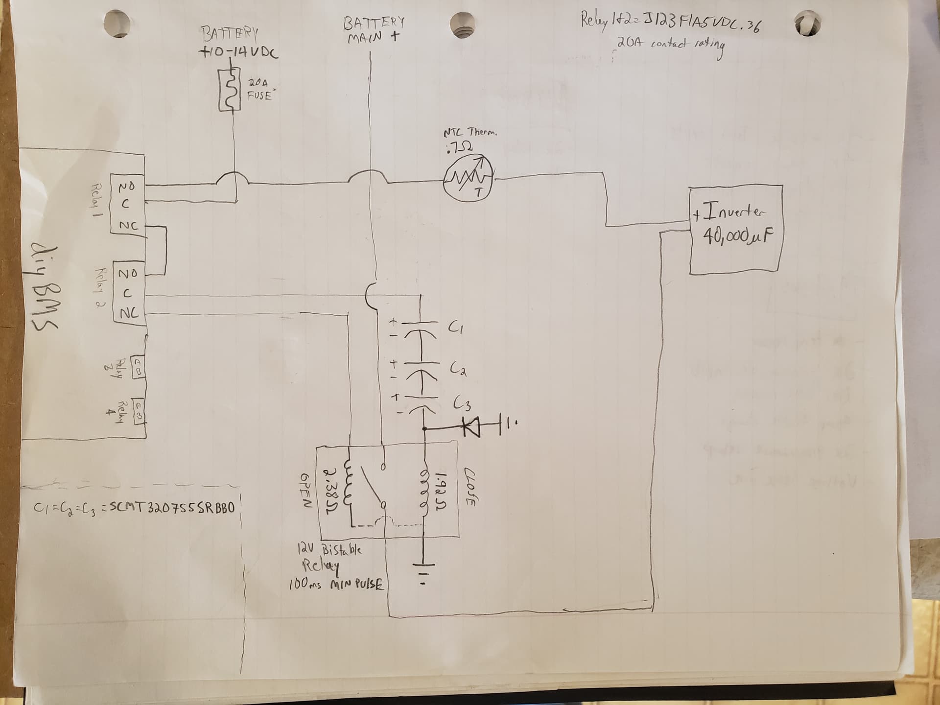
I understand this amount of power drain might seem trivial for most but for standby systems without ubiquitous charge sources it can add up if continuously held ON. I actually will be using a bistable contactor for battery isolation. But rather than use Relay1 and 2 for the pulse on/off i want to use supercaps to drive the contactor so that upon any power or signal loss it will still guarantee battery disconnect as done here 12V Latching Contactor & Universal BMS Control Board - YouTube. This also frees up a method to automatically precharge the inverter bus through Resistor or NTC Therm prior to load connection. Firing both relays simultaneously with Relay1 set to pulse should give the result im after. Stuart at one point mentioned the pulse is ~200ms though i couldnt figure out where in the code this could be confirmed. That should get the caps in my scenario charged to at least 95% (t=3RC) before connecting the battery
There are nice bistable relays here:
http://www.layher-ag.de/images/downloads/relais/Bistabile_Leistungsrelais.pdf
1 Like
Pulse is approx. 250ms - depending on the the FreeRTOS scheduling inside the ESP32.
pulse_relay_off_timer = xTimerCreate("PULSE", pdMS_TO_TICKS(250), pdFALSE, (void *)2, &pulse_relay_off);
There’s also the possibility of a pyro fuse as found in cars - but that really is the option of last resort!
@menningd You seem to mean SCMT32D755SRBB0. (The difference between your letters D and O isn’t immediately obvious.)
What are the two wires going to your “inverter”? Are they connected?
I’d add a flyback diode to the Open coil. Otherwise you’re likely to fry the relay contact.
Why do you need Relay 1 in the first place? Seems to me that simply connecting Rel2/NO to +12V should work; precharging the inverter with 12V doesn’t accomplish that much if the main battery has 48V.
Why a 20A fuse? if the coil has 2 Ohm resistance you won’t see more than 6A or so, and that only for a short time, so a slow 5A fuse would work just as well.
Yes they are both connected to + bus.
This contactor conveniently has them built in. Shallco BR-300-12-1-34
Relay1 holds Relay2 off while the inverter caps charge up (200-250ms according to Stuart ). Then the precharge turns off and the contactor gets the close pulse (actually there will be a ~100-110ms delay after the precharge turns off before the contactor coil will close the contact). I should have given more info, this is a 7.3 kw 12v system for a boat.
20a is the rating of the largest drop in replacement for Relay1&2 i found. If somehow relay 1 stuck on it would draw 20a based on 14v battery and initial .7 NTC thermistor resistance. True I probably could downsize slightly based on just that momentary draw.
Hi Billy_Boes,
just reading this topic of the junctek ah counter and trying to integrate it with the diybms.
Did you have any success in doing this.
I have a diybms and a current shunt that i am setting up at the moment, but have also installed a junctek, ad must say i really like it, it woul be great in future maybe to have the junctek talking to the diybms for some that havent the skills to make up a diy bms current shunt.
If your is working, what did you have to do to get it working,
Thanks
Hey Anthony,
I abandoned the junctec shunt in favor of the diybms shunt in my system, but may dust off the junctec so I can monitor my solar current separately. I’ll keep you updated on my progress.
ok, thanks.
Ive got a diybms shunt too, but currently hving a few slight issues with it. I need to get the latest code onto it and i havent programmed with updi before and struggling to find a youtube vieo on how to use a usbttl adaptor to use as an updi programmer, For me a steep learing cirve.
I also need to install another 2 complete home built battery systems with dybms and shunt to communicate with canbus t hybrid inverters.
Got to get hold of another 2 built shunts.
Thanks.
5 posts were split to a new topic: Single board design
Those Layher relays are interesting, though I guess they’re mainly useful for off-grid applications.
I asked them about pricing, specs etc. The Layher 400-200-xx21-241 (xx is the nominal voltage, 12/24/48) is €95 and needs hefty capacitors and a relay that can take the current you need to turn it on / off. On the other hand of course it doesn’t need any power to stay switched on.
Our standard EV200-style contactor is €30, works up to 900V instead of 60, can switch up to 500A, and can be switched with a single SOT23 transistor. It eats the equivalent of 5€ or so of power per year.
Thus the break-even is after ~15 years … oh well.
Has anybody attempted to connect two controllers to a single CerboGX via CAN? Not after DVCC. Just would like LVC/HVC via CAN and to see basic bank/cell stats from within the Victron environment
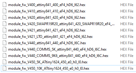
how to program the v4.5 module? i have the programmer for the shunt but where to download the file for the module?
In the releases…
https://github.com/stuartpittaway/diyBMSv4ESP32/releases/tag/Tag-2023-02-21-08-55
Download the ZIP file Compiled_Firmware_2023-02-21-08-55.zip
Inside that Modules/Hex and the files are there.
1 Like
What module fimware corresponding with firmware ESP32 in this release?
https://github.com/stuartpittaway/diyBMSv4ESP32/releases/download/Tag-2023-02-21-08-55/Compiled_Firmware_2023-02-21-08-55.zip
i have v4.40 cells boards, now with esp8266 controller. Exist 3 variants on this release…
Please publish schema UPDI interface to esp controller, published is only board for programing…
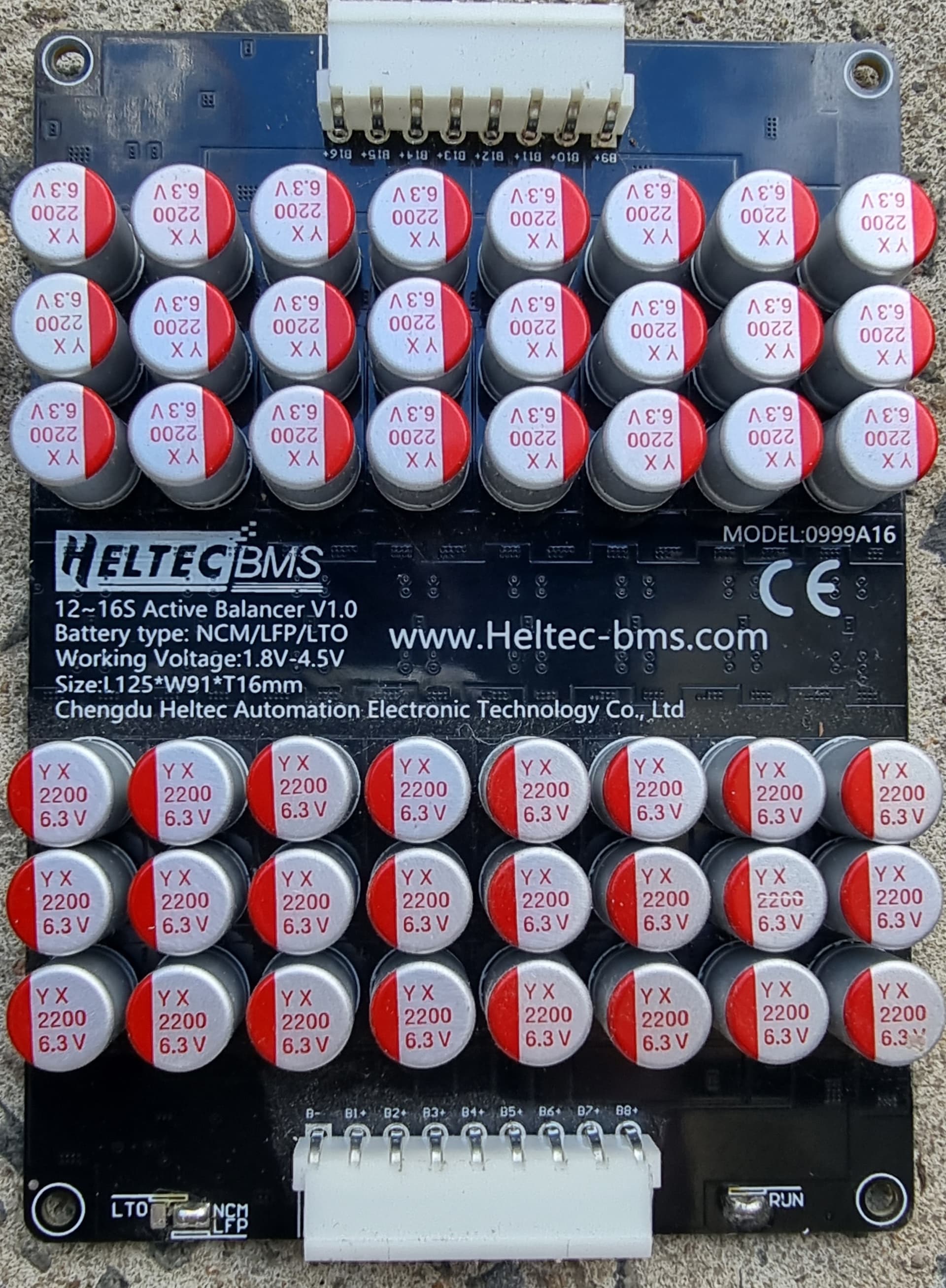
They often have a soldered jumper allowing you to replace the jumper with a relay for S/W control.
It’s the RUN jumper in my case:
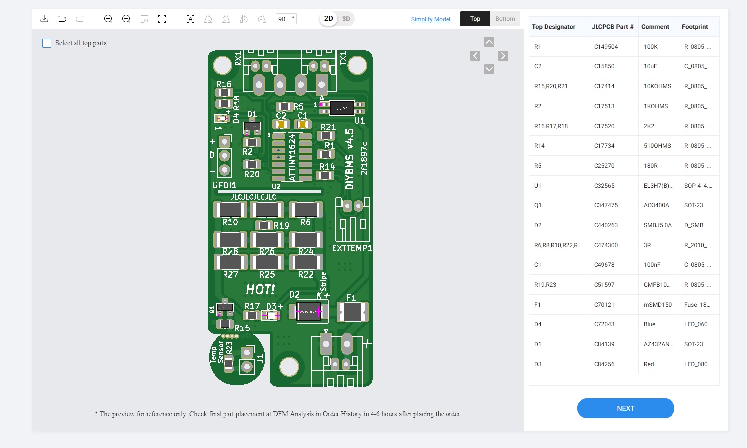
yes, d2 is in wrong position. White stripe on diode marked cathode. Diode is in zener mode (reverse polarity), its no normal diode…
Yes, probably. I’ve given up trying to correct them on that part, they keep swapping the pin orientation around. It’s a TVs diode and they don’t appear to understand.