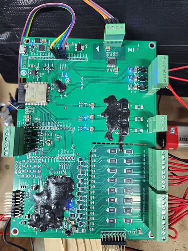
As a company I have managed to order the INA228 chip and ATTINY1624-SSU in large quantity directly from the manufacturer. i will have available 1000 INA 228 chips and 1000 ATTINY1624 ready for sale.
As a side note , I want to work with you into refining this bms into something that will suit my needs. My abilities to design the pcb is awful. The amount you will put into helping me will not be free because I will pay you. If you are interested drop me a message so we can share contact details.
@lorenzo what do you have in mind that doesn’t suit you right now?
Well , first of all i would like a single board design , but a member helped me with his own design so that is fixed. I would need a board with Nchanel mosfets , same as a comercial BMS to control the charging and diacharging via Diy BMS. I have like 800 NChanel mosfets in the shop just laying arround , radiators , fans.
What i need right now is a board with mosfets , 2 inputs for charge enabled , discharge enabled and a preload resistor.
Also on the cell monitor would be nice , if it is single board design , to put a conector for a daughter board with bigger mosfets and bigger resistor for cell balancing with 5A , or higher. The signal would be picked up from the existing mosfet on the board and a jumper would be needed to select the internal balancing resistors or the external ones.
Rj45 conector would be nice between the cell modules, shunt and controler and from controler to the mosfet board.
I have 46 Kwh of brand new lithium Ion cells installed with crapy Daly BMS. 23 of them and i already changed a few because they died and still have like 80Kwh more not installed.
If you can design it , regardeles if i pay you for the time spent , you are free to share de designs with everybody.
I assume so.
Continued via PM.
I have in tests a bms , single board design ,with esp, with shunt , OLED display , awsome piece of work. But the firmware is crap, at least the logic inside.
It has 3 outputs , emergency for emergency shut down , chg mos , dsg mos.
When charging , if i set OVP to 3.9V and OVPC to 4V , in my head i would expect that the bms would stop charging when OVP is reached , and emergency trigered when OVPC is reached. In reality , this crap behave as follows:
One cell reaches 3.9 V but reaction
All cells reach 3.9V no reaction
One cell reaches 4V , no reaction
5 cells reach 4V no reaction
12 cells reach 4V , 1 cell reaches 4.03 , 1 cell reaches 3.98( cell 14) but no reaction.
12 cells reach 4.1v , 1 cell 4.15 and cell 14 reaches 4V finaly and the bms trigers the emergency shutdown.
So in essence the bms waits for all cella to go over 4V in order to stop charging.
In my head the scenario would be diferent , one cell reaches OVP at 3.9V , the chg mosfets would be off , if alarm state goes away resume charging. If voltage reaches OVPC the trigger emergency and wait for user input
The chg and dsg mosfets are trigered only by OVCP.
On the discharge the things are backwards.
If One cell reaches UVP at 3V nothing happens but if one cell reaches UVPC at 2.9V the the emergency is trigered , the battery wont charge or discharge until user reboots it.
Things shoult work like the desired charging function.
One cell reaches UVP , stop discharging mosfets and resume when alarm goes away ( battery is beeing charged). If dsg mosfets are off , but UVPC is still reached then triger emergency and wait for user input.
Over curent does the same thing , trigeres the mos and emergency and waits until rebooted.
Same for temperature , the thing shuts off and stays that way.
In my opinion is not usable.
