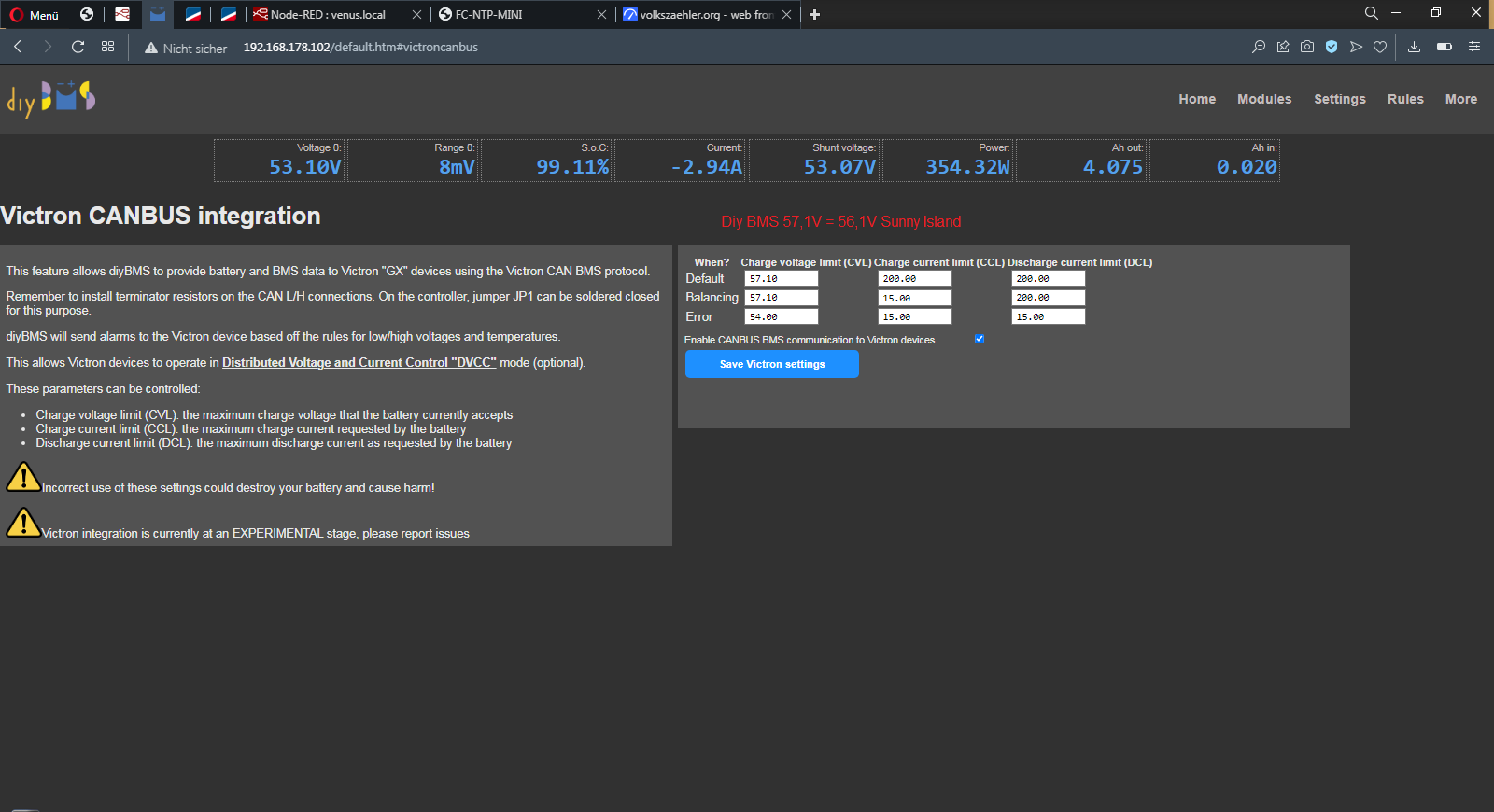
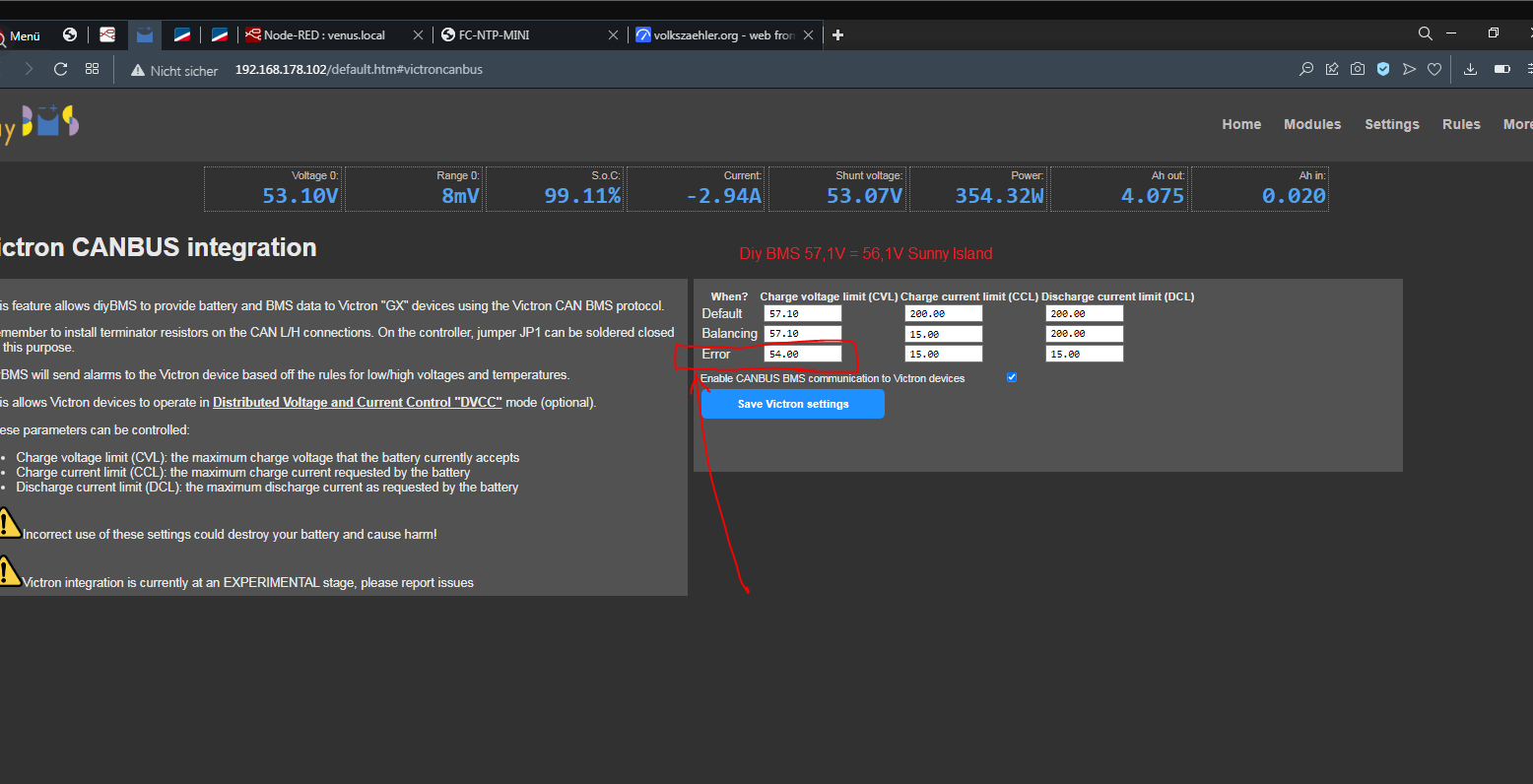
here it is
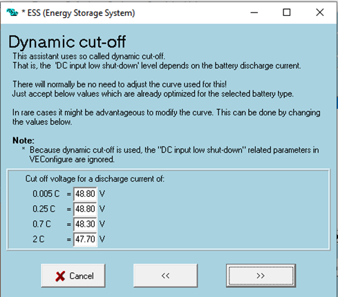
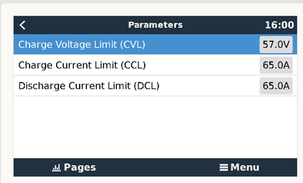
i set 57,1V max charge voltage this is 56,1V in my SMA Sunny Island as i told a bit buggy
if you have victron you can set the real voltage
i have both sma and victron mppt 450/100.
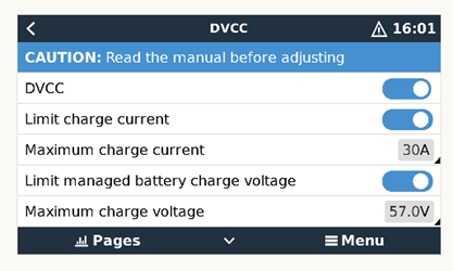
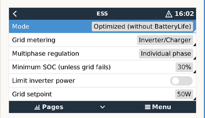
for victron i set a max dvcc voltage of 56V in the venus os so the battery will not overcharge
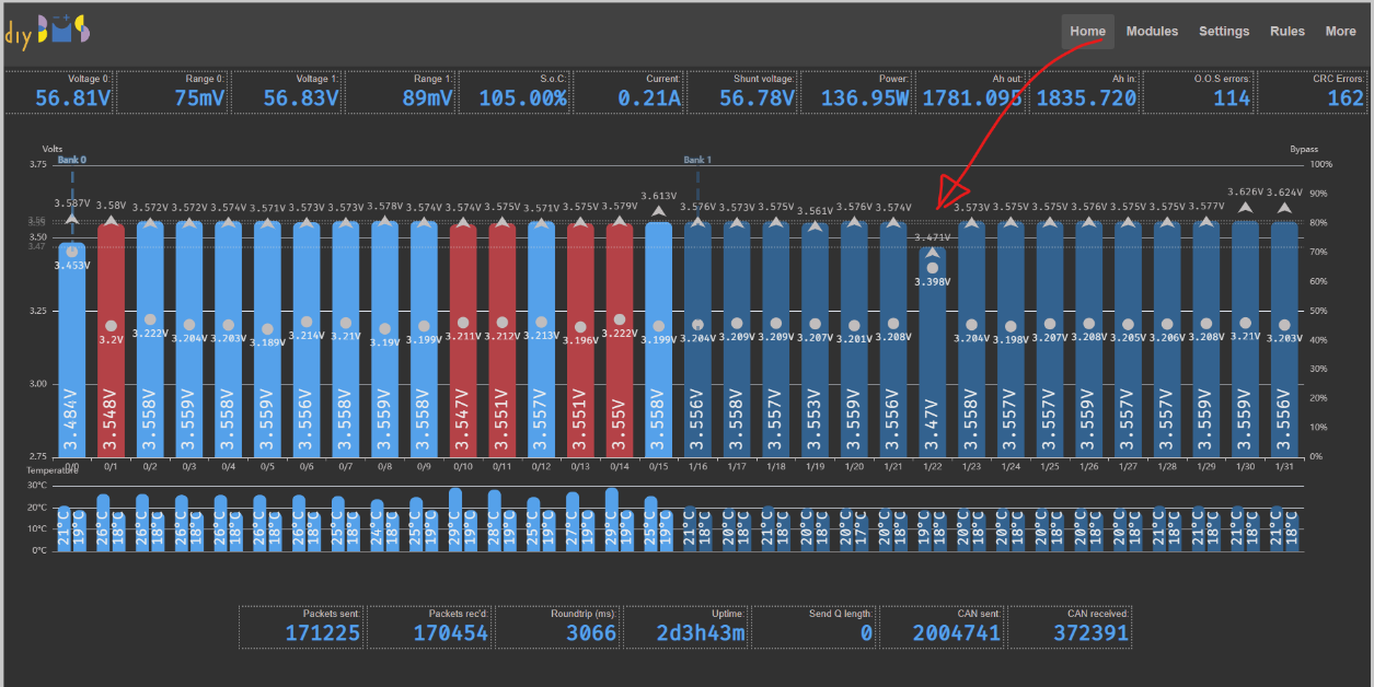
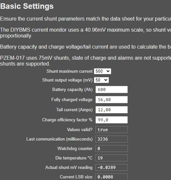
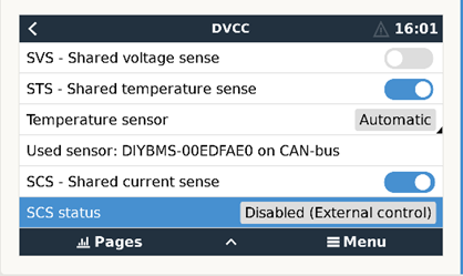
I almost have it, with a laboratory power supply, I am feeding the lowest cell to bring it to the level of the others, at 3.55v and from there go increasing the battery voltage up to 57v (now 56.8V) but I have doubts if I have the Victron, ESS, DVCC and DiyBMS parameters well configured.
It would be too much trouble if you check them, and tell me if everything seems to be fine, or should I change something?
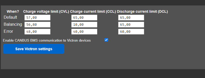
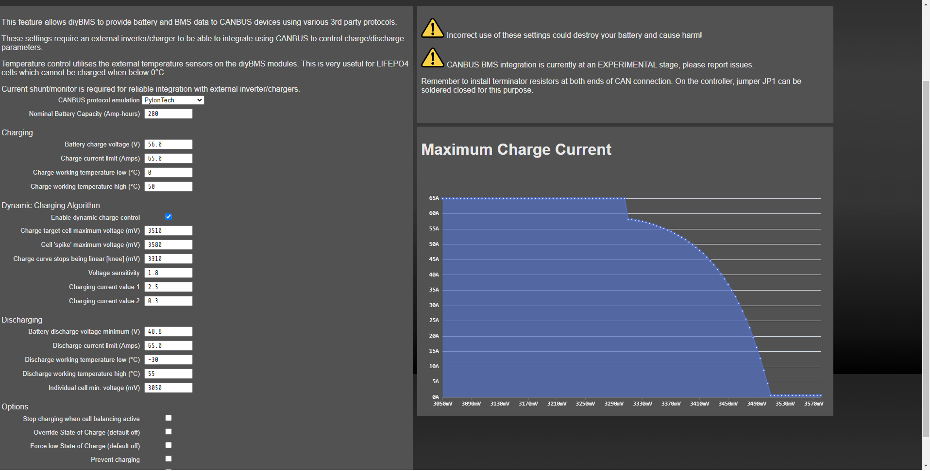
All, just for information - the next release of the controller code includes a large re-write of the CANBUS communication - along with Victron and PylonTech battery emulation.
Heres a screenshot of the configuration - its not ready for release just yet.
@stuart Hey Stuart, hope you are well,
I think I have found a bug in the ESP32 DIYBMS Controller.
I am running a 14S2P battery bank, and the round trip communication is 5800ms,
I have rules configure for cell under/over voltage and bank under/over voltage
If I power up the controller or reset it from the UI, the system will come up with the message waiting for modules, and becasue not all the modules have reported in the Controller registers the bank as under voltage it triggers the rule which trigger the shunt.
I have done several test and this only happens with the bank under voltage.
Is it possiable to have a delay before triggering the rule, either we can configure it gloabally, or you can program it in at startup that the system should allow for 20-30sec before starting to monitor the rules.
Hi guys ,
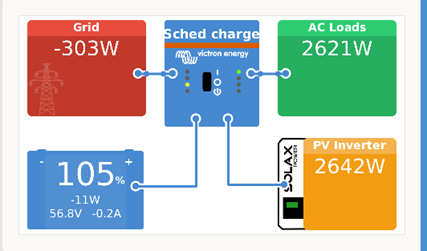
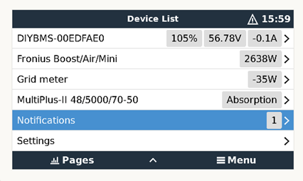
Please excuse my off topic question, but I just seen something in one of the “Chapulino” pictures that catches my attention.
There is a picture from Victron GX screen showing a Solax Pv inverter
Also in the device list there’s a Fronius Boost /Air /Mini inverter seen by the Victron GX
My question is how did you managed to connect the Solax to the Victron gear and collect data from The Solax pv inverter.
I have asimilar setup with a Victron Multiplus II and a Solax 3.6 td on the input of the Victron and would like to have the data on the CcGX
Fun times,
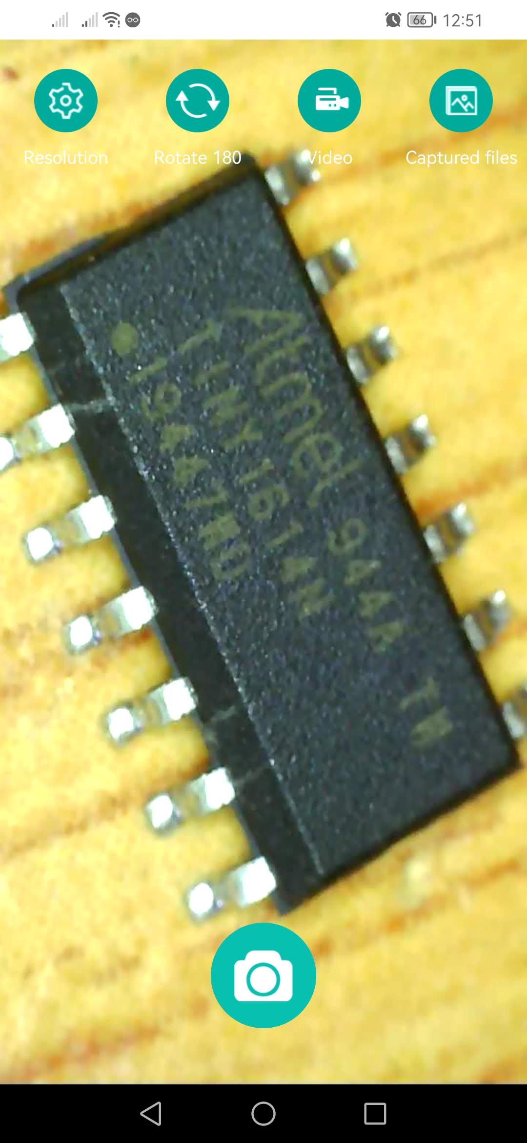
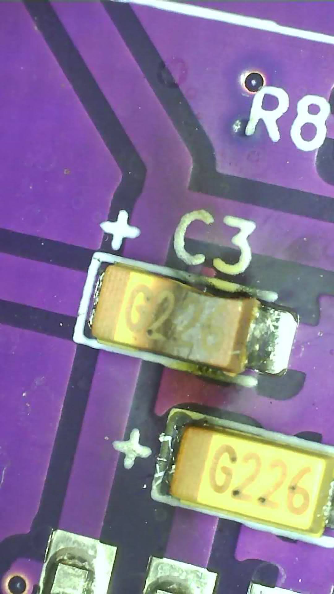
I have just managed to get some magic blue smoke from my brand new ESP32 DIYBMS Controller From what I can see and what I have tested the ESP32 Controller is fried, and I found 1 CAP C3 in the board that’s blown.
22uF 6.3V C3,C4 C190381
Not saying this is the reason for the cap going, it poped as I connected my 5V to the board, I am using a regulator which is regulating from 48v to 5v, as I connected the controller it blew the cap which shorted and then blew the regulator,
I am going to replace the cap and test the board to make sure nothing else is popped,
I can’t get that exact cap locally, but I am able to get the following, would either of these work ? 22uf 10v 47uf 6.3v
Hi luxprospector.
there is a guy who has developed a module with an esp32 that replicates the original solax wifi pocket, but at the same time allows Victron to identify it as an inverter (at first as if it were a Fronius) even though I modify the image presented by Cerbo so that it appears as a Solax inverter.
At the moment he is only compatible with versions of V1 and V 2although he is already working on the Pocket Wifi of Solax V3.
Since this is not the subject of this thread, if you want, send me a private message and I will provide you with some information.