i ordered may 2022 the new style board
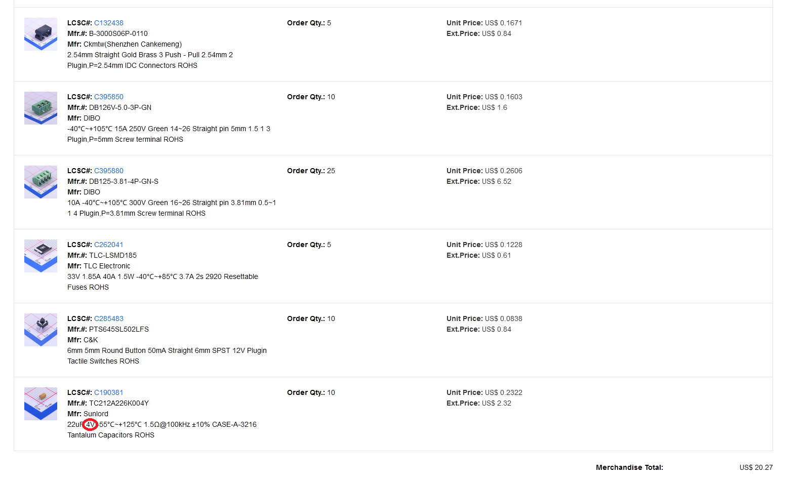
the c3 c4 were not in stock at jlcpcb so i ordered them at lcsc and confirmed now there is the same issue 4v part
should i order and replace the corect ones?
thats a problem
because it affect others too i ordered 5 pcbs and sold 3 of them…
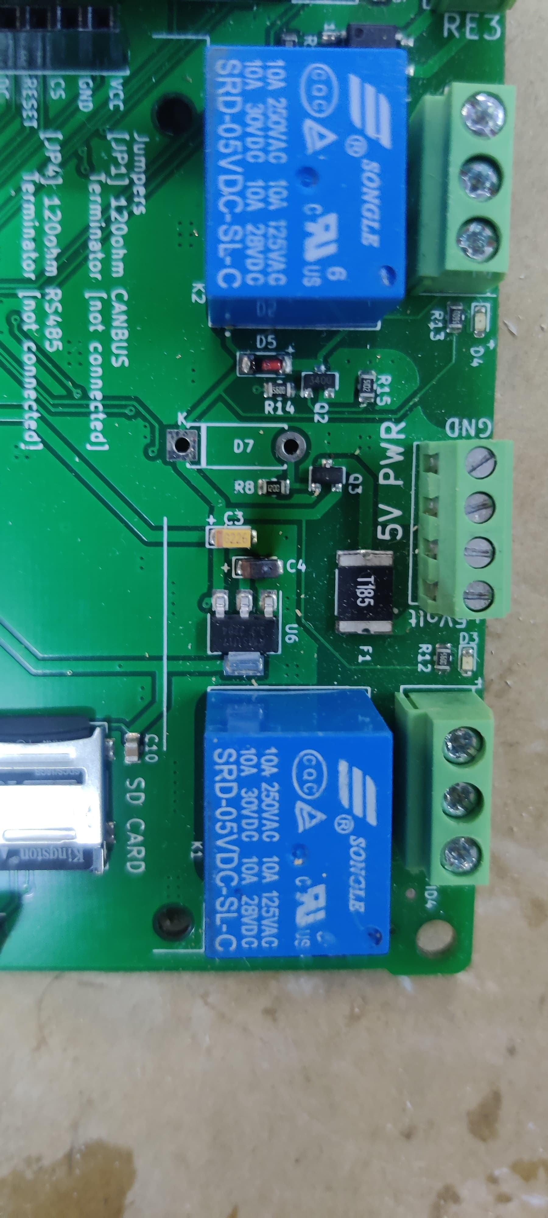
Hi @voltmeter , technically its only 1 of those caps that shouldn’t be working correctly at 5V - the other cap only has 3.3V across it.
Rolf’s example is the first I’ve seen problem, so it probably means either people don’t use the 5V socket/plug very much (instead using direct USB to the ESP32) or the 4V part is okay up to a higher voltage - but over time is likely to eventually fail.
so the one issue cap is c3 need to be a 6,3V?
i will change it
because if that part fail and the controller goes off, then i have a blackout in my offgrid house
because my inverter need a canbus signal to be on
it work now for almost a year, but you never know when it will fail because of exceeding the specs
@stuart This is a shot in the dark,
I recieved a new ESP32 and flashed it, then replaced the CAP and connected the ESP32 to serial console, but I am getting this error,
Maybe it’s an easy fix or I’ll have to order a new Controller
Not sure if there is any specific testing I can do it identify the fault
_ __
| o |) |/| (_
(| | / |) | | __)
/
CONTROLLER - ver:e843bcb23f6aa0b0b75df78a05d59a0f5dc46bc7 compiled 2023-01-03T10:07:59.024Z
ESP32 Chip model = 1, Rev 1, Cores=2, Features=50
I (26) diybms-hal: Configure I2C
I (28) diybms-hal: Scanning i2c bus
I (42) diybms-hal: TCA6416A not fitted, assume v4.2 board
E (42) diybms-hal: TCA9534APWR Error
E (42) diybms-hal: SYSTEM HALTED
ESP_ERROR_CHECK_WITHOUT_ABORT failed: esp_err_t 0xffffffff (ESP_FAIL) at 0x4008e4af
file: “src/HAL_ESP32.cpp” line 128
func: esp_err_t HAL_ESP32::writeByte(i2c_port_t, uint8_t, uint8_t, uint8_t)
expression: i2c_master_cmd_begin(i2c_num, cmd, pdMS_TO_TICKS(100))
ESP_ERROR_CHECK_WITHOUT_ABORT failed: esp_err_t 0xffffffff (ESP_FAIL) at 0x4008e4af
file: “src/HAL_ESP32.cpp” line 197
func: void HAL_ESP32::WriteTCA9534APWROutputState()
expression: writeByte(I2C_NUM_0, TCA9534APWR_ADDRESS, TCA9534APWR_OUTPUT, TCA9534APWR_Output_Pins)
ESP_ERROR_CHECK_WITHOUT_ABORT failed: esp_err_t 0xffffffff (ESP_FAIL) at 0x4008e4af
file: “src/HAL_ESP32.cpp” line 128
func: esp_err_t HAL_ESP32::writeByte(i2c_port_t, uint8_t, uint8_t, uint8_t)
expression: i2c_master_cmd_begin(i2c_num, cmd, pdMS_TO_TICKS(100))
ESP_ERROR_CHECK_WITHOUT_ABORT failed: esp_err_t 0xffffffff (ESP_FAIL) at 0x4008e4af
file: “src/HAL_ESP32.cpp” line 197
func: void HAL_ESP32::WriteTCA9534APWROutputState()
expression: writeByte(I2C_NUM_0, TCA9534APWR_ADDRESS, TCA9534APWR_OUTPUT, TCA9534APWR_Output_Pins)
ets Jun 8 2016 00:22:57
Thanks @stuart , these are devc boards, I suspect with the short of the cap and then shorting my 5v regulator, the regulator popped and suppliied 12v to the controller, I suspect more than just the cap got damaged
I’ll just wait and order a new controller, is it worth waiting for the next release of the controller ? Are there going to be significant changes, or is the current release just as good ?
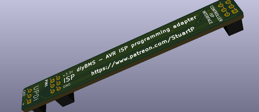
Unfortunately not yet - the hardware should be okay, but the code doesn’t exist in the controller. Stick to using a USB Serial cable for now - easy enough to do, take a look at this…
Working on my battery build and I have a couple of questions. It’s quite big with 104 cells in series 4 separate packs, which I’m hoping can be configured in software. I have some contractors that I would like to connect to the relay rules. Is there still somewhere I can hook up a relay board? The controller board seems to have two but I need more.
Since it has taken me a while to collect all the parts I have controller v4.2 and module v4.4.
Also curious if you have any documentation for your CAN BUS communication. Thanks for all your amazing work!
Not on the 4.2 controller - it has 4 relays on board, two mechanical ones and two digital ones - the digital ones are only low current, but you might be able to use those to drive an input to a mechanical relay?
Is there a version compatible with my setup that would support more relays? I need to control at least 8 but 12 would be ideal. If not maybe using CAN BUS to control a relay board might be possible. Using an Arduino or similar chip to control the relay logic.
I logged and controlled next home automation via MQTT connected diybmsV4 controller. Home asistatnt is easy way… Not relay, if battery SOC high, homeasisitant display this, and set ON air condition or WIFI thermostat in electric heating. I not need more relays…
Sadly because of the setup MQTT will likely not be possible. CAN BUS is the only communication line that would work but I can’t find any documentation on the CAN communication protocol the bms is using.
I would think that if it can do Victron Integration there should be a way to just send out other information on the CAN BUS. Maybe it’s not already integrated but I’m sure it could be added. @stuart is this possible to use CAN BUS for relaying data on the bus? Maybe I could make some modifications to the code to get this working?