@stuart
i have the Release-2021-09-06-09-56 on the diy bms shunt
now i found many newer versions.
what have you changed there, does it worth the upgrade?
I’ve made changes to improve the calibration, it can also now do a daily amp hour count, and state of charge has been improved.
This will also need an update to the controller, which is not yet released.
thanks for the information
i will wait for the new controller firmware then update the shunt
can you make this compatible for 4.4 modules?
If it is only about changing the position of the connectors and repositioning the tracks with the same configuration. Give me a little time and I’ll try, the only question is that I won’t be able to test the new board until the end of February when the Attinys arrive, so it will be a design without final verification, with the risk of having me wrong about something
Let’s see if someone can help me.
About a week ago I had a little problem with the Shunt, nothing serious, it resulted in a replacement of the communication cables between the shunt and the controller.
Take advantage of installing the latest version 2023-01-03.
But I am observing that the battery charge is limited a lot.
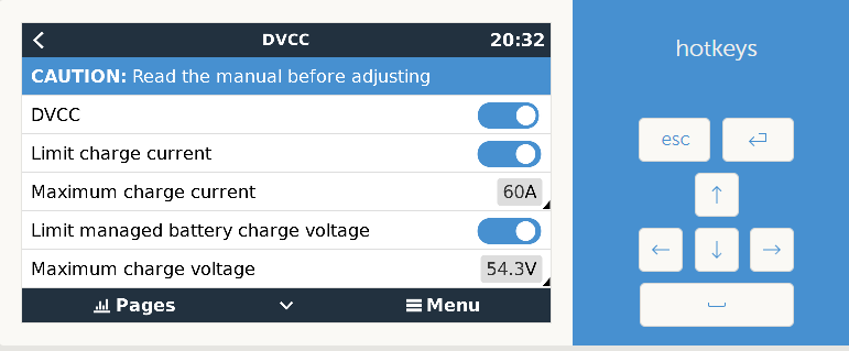
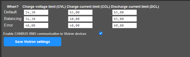
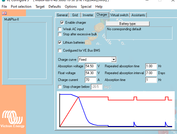
I have configured the Multiplus for a maximum load of 65A
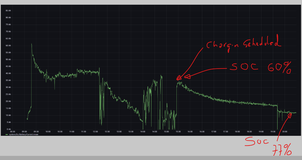
But even with the battery at 40% charge, the system significantly limits the charge. I would understand if the system limited the charge in ranges of 90 or 95% but not before. I don’t know if I have something wrong configured in DIYBMS and this is the cause,
To do a test, I have put the system on charge from the network (Schedulde Chargin). But it only charges at 15A.
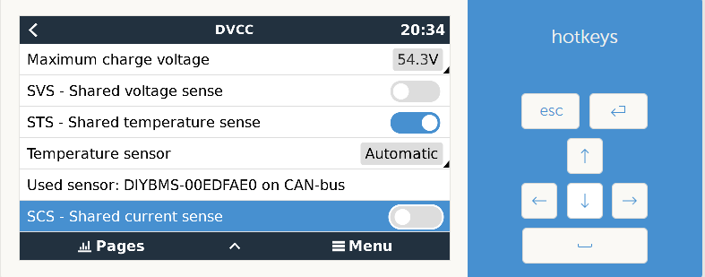
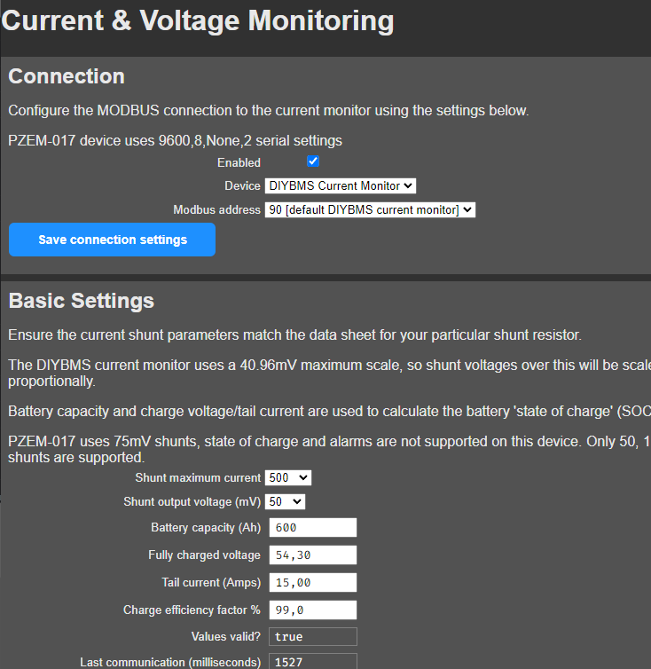
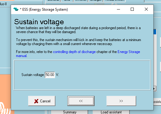
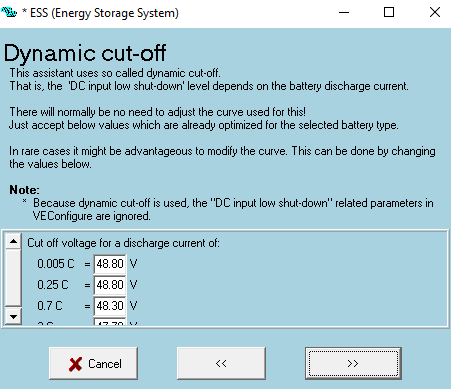
I take the liberty of sharing configuration screens
For informational purposes I have a LifePo4 16S 2P battery
Thanks in advance
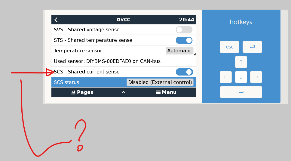
Last I have a question about whether the SCS Shares current sense should be enabled or disabled in a battery controlled by the DIYBMS System?
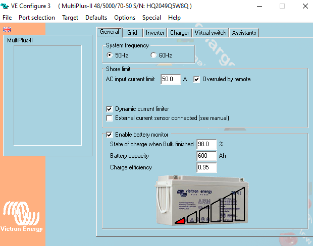
What did you set in the Victron with the Victron Software by remote via the Victron Portal?
There are some settings which are only available in the software.
And they overrule the visible settings in the Victron console
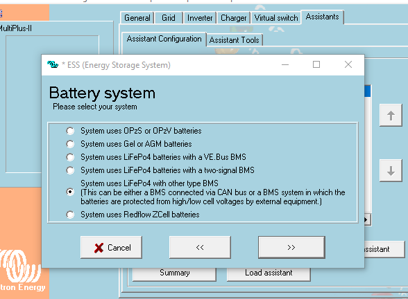
OK. You use a 16S Lifepo System.
Guess:
Fully charged: 16x3.65V= 58,4V.
You use 54.3V max.
The system does not know there is a 16S system and expects a 15S system.
The charge curve decreases early.
Set the max charge in the Victron to 58.4V.
Float a little bis less.
In the BMS you can let it like it is. The BMS overrules the Victron settings.
If this does not help play with the settings of the charge curve.
I hvae a 16S system with a 3000 Victron.
Works with the max charge of 32A.
And with my settings I expect it would work with a 5000 Victron also with 70A.
stuart wrote to my question about upgrading the shunt:
"I’ve made changes to improve the calibration, it can also now do a daily amp hour count, and state of charge has been improved.
This will also need an update to the controller, which is not yet released."
–
and 54,5V is not enough for 16s life you have to set 56V minimum for full charge
Thank you very much for your answer, originally it had a higher voltage around 56v but when it went from 54.3 the cell voltages deviated too much and DiYBMS could not balance them. But the charge was produced properly, something should have been improved In the system I don’t know if it is in Victron or in DIYBMS and now it is not like that.
I will follow your advice and increase the maximum load voltage to at least 56v
Rafael. If the cells drift much during charge it may only have 3 reasons.
- The cell were not properly top balanced. Do a top balance.
( All cells parallel with a laboratory power supply at 3.65V for some weeks… ) - The cells have diffrend capacity. You may got poor quality.
- You have weak contacts at the cells which do not charge well. Its not so probably.
The Victron provides the charging current and voltage.
The DIYBMS tells the victron how to charge.
If one cell voltage runs over the max cell voltage the BMS burns energie at this cell.
And it tells the Victron to slow down the charge current to your setted value.
Definitely: if your cells are not to be balanced in a good mannor you have a cell problem.
Not a BMS or Victron problem.
Which cells do you use?
I rule out the problem you mention, the cells are CATL of 305Ah of good quality (purchased from a reputable Chinese supplier (BASEN). At the time of starting the battery, a maximum charge was made in parallel to 3.6V, this was ago a year and a half or so.
At the time, not a long time ago, I thought that the reason was that DIYBMS was not able to balance from 3.4V. Since I didn’t need to rush the maximum charge of the batteries, I decided to limit the charge to that point. But it seems that the improvements and updates of the driver are now having an effect that they did not have before (I have been more than a year without updating the driver ersion).
Today I am charging the battery to the maximum, I imagine that in about 4 or 5 hours I will complete the charge to 56V and I will tell you if they start to get out of hand after 54.5V
I take this opportunity to also thank @voltmeter for his comments
I guess you will not have success.
At 56V the cells have 3,5V. This is in an area where the cells can have everything.
Between 75% and 90%.
And this is what you can see when it tries to balance.
Some cells are already more than 3.5V and start burning energie.
The BMS tells the Victron to reduce charge current.
Again: you will only be able to see an improvement after top balancing.
In a manor that you switch all cells parallel and set them under constant voltage of 3.65V.
For longer time. 1-2 weeks.
Thereafter you can reduce your max voltage as you demand.
You will see an improvement.
3,5v is “ok” for balancing if the charge controller can only charge to this voltage
but if the charger can charge and hold the voltage on 3,6 for some hours then automatically reduce to 3,4v this would be better.
i am using the canbus communication from diy bms and there is only one full charge voltage so i have 56V it does the balancing. i have replaced one cell, now it is well balanced again.
but im waiting for stuart to improove the canbus function, it is a bit buggy now
@stuart Hi Stuart,
I have a question about the new controller and ESP32,
on the board between the 2 relay terminals, there is a 5V power input terminal.
Is this an alternitivate terminal to powering the board and not having to use a USB cable ?
Thanks
What din rail mount boxes are you using for the new controller and shuts ?
@voltmeter what is your canbus configuration?
Can you tell me what is the maximum load value (absorption) in your installation and minimum value and the configuration of the canbus part in DiyBMS?
I don’t quite understand these values to configure
Ok. A defective cell.
I run the canbus. No bugs. Works fine.