there is a new release from today which fixes a temperature issue.
It won’t fix this issue, that’s the controller rule which has a bug in it.
Hello
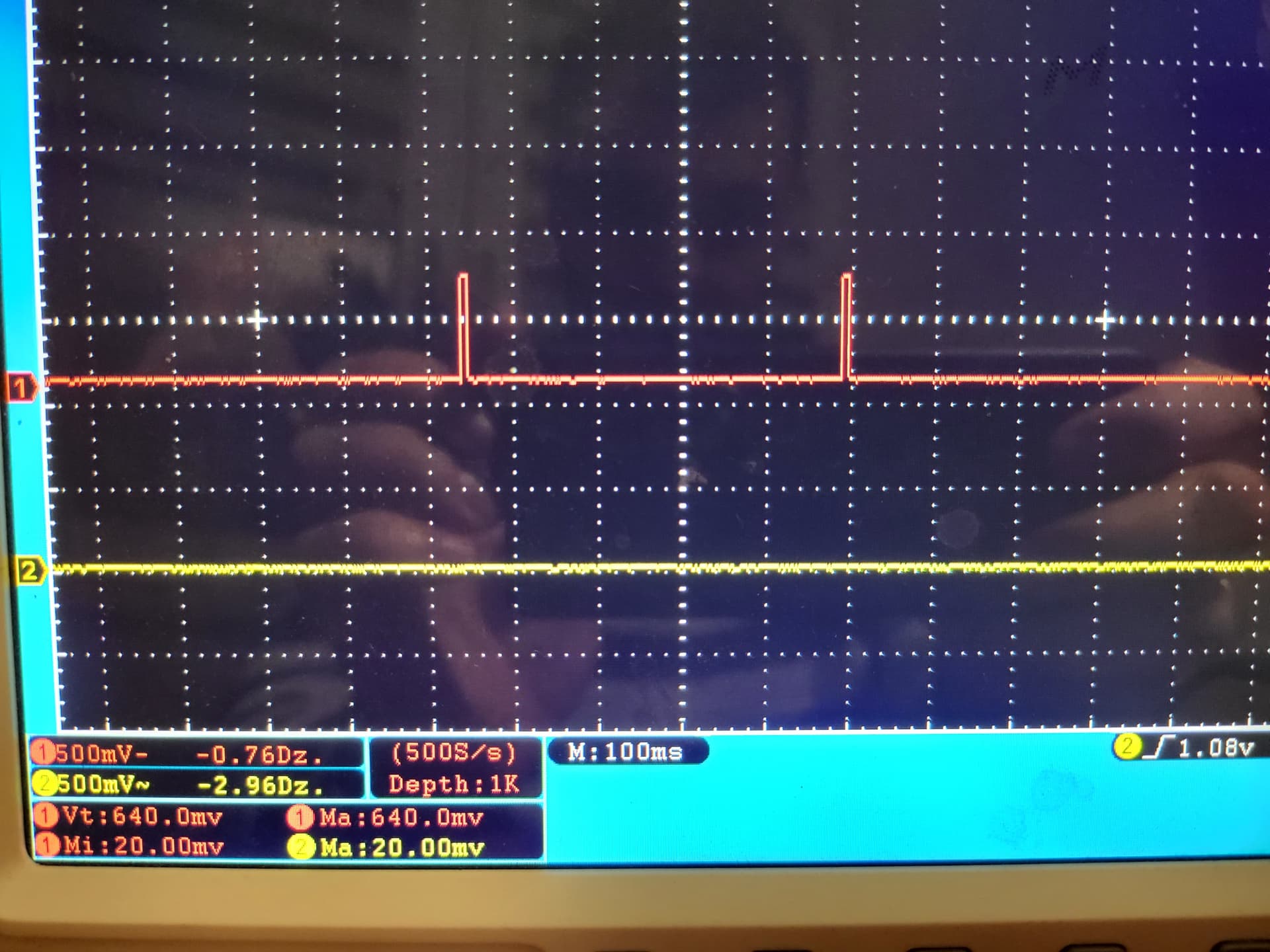
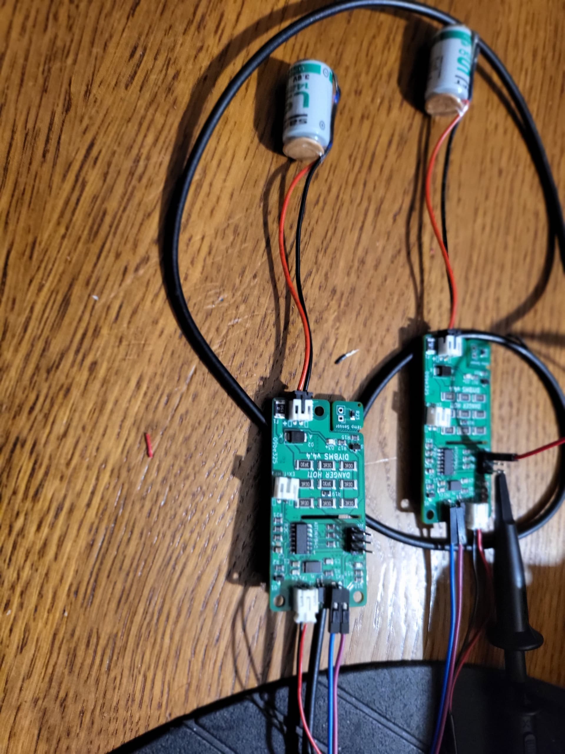
I creating first project with diyBMS esp32 + 2s 14250 battery for test. Modules v4.4, communication speed 9K6. The problem I have is the lack of reading from the temperature sensors. I checked 10 different modules … no reading on each (external temp not fitted and module temp -40). Voltage reading is ok. In the oscope i see signals that goes to attiny. Soldering of the attiny seems ok. Can you have idea whats could be problem?

This was fixed yesterday, please update the modules code.
Thanks for help. After update modules, working well.
By the way, great project.
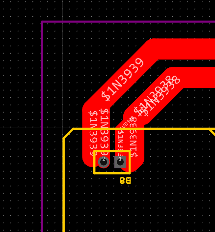
As a tribute to the new V4.5 modules I am designing a new board to house 16 modules. and be able to cool them with fans

On this occasion I have chosen to place the modules and route the tracks by hand to obtain a cleaner board, without crosses or vias and that I think will allow 9K communication
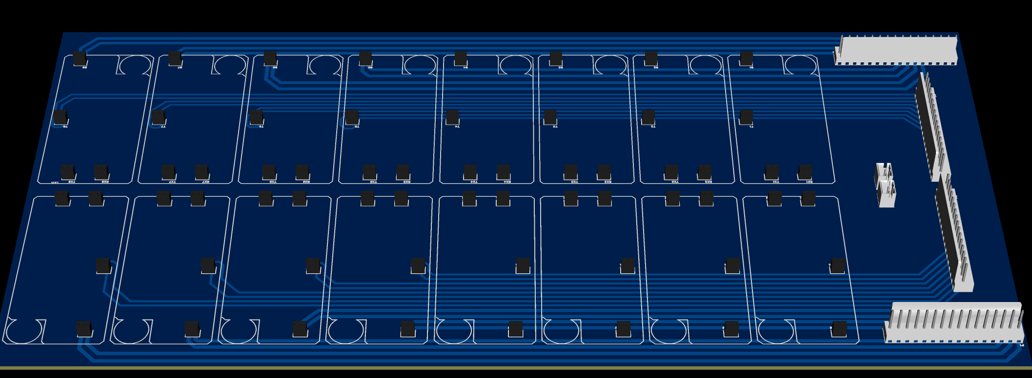
Stuart I have a question, 50 mill for the drum tracks and 30 mill for the rest of the tracks is it correct or should I make them wider?
looks good but why to use 4.5 modules if you have the 4.4
could you make a version of this board for 4.4 modules too?
looks much cleaner
you could place the cell conectors in the middle, up and down
so the way to the modules is much shorter there will be less voltage drift
i would also double the paths for the balance part
I also thought about the option of putting the battery connectors close together, but the difference between the distance to be covered by the battery tracks is small, just about 20 cm maximum (proportionally to the distance that the cables that go to the batteries then cover is small And I prioritized shortening the communication tracks and moving them as far away as possible from the rest of the tracks for less interference.
As I use the 2mm connectors for the connection, I am a bit limited in terms of the width of the battery tracks, more than 60 mill, I could use the new 3.81mm ones and thus I could widen the battery tracks, but it is not easy find cheap connectors at that distance.
I don’t really know what you mean by “i would also double the paths for the balance part”
well, if you test this new bord let us know if 9k is working
you dont have to make the track wide direct to the 2mm connector its the distance that have to be wide for less resistance.
you can have this normal size of track a few millimeter to the 2mm connector
with the balance part i meant the connection to the cells where the current flows
thats why the short distance to the connector is important you can calculate a cross section of 0,5mm² would be good but i dont know how wide this will be on the pcb, maybe 5mm wide.
i was thinking to modify your old style pcb cut all the paths to te cells and manualy solder wires from behind but if you are making a new pcb im happy with that idea of making the tracks for the balance current much wider and shorter
so this is compatible with the 4.4 modules too?
I have not checked, it is possible that Stuart has not changed the location of the mm pins in the new module, tonight I check and this? would it work?
looks much better
at the other end you have to optimize because of the multi pin connector
maybe you can place an other with greater pin distance

Its completely bad idea!! Long wires without fuses directly on battery.
I have modules directly on cell screw, only comunication cables…
I don’t argue if it’s a good or bad idea. In my particular case , the system works great . I have had it like this for more than 9 months for a 2 x 16S 600Ah (Lifepo4) system. And the operation is impeccable, it is true that some battery cables are almost a meter long, but I put quite thick 18AWG cables. The download limit that each module has means that despite the distance, the efficiency of the modules is not affected.
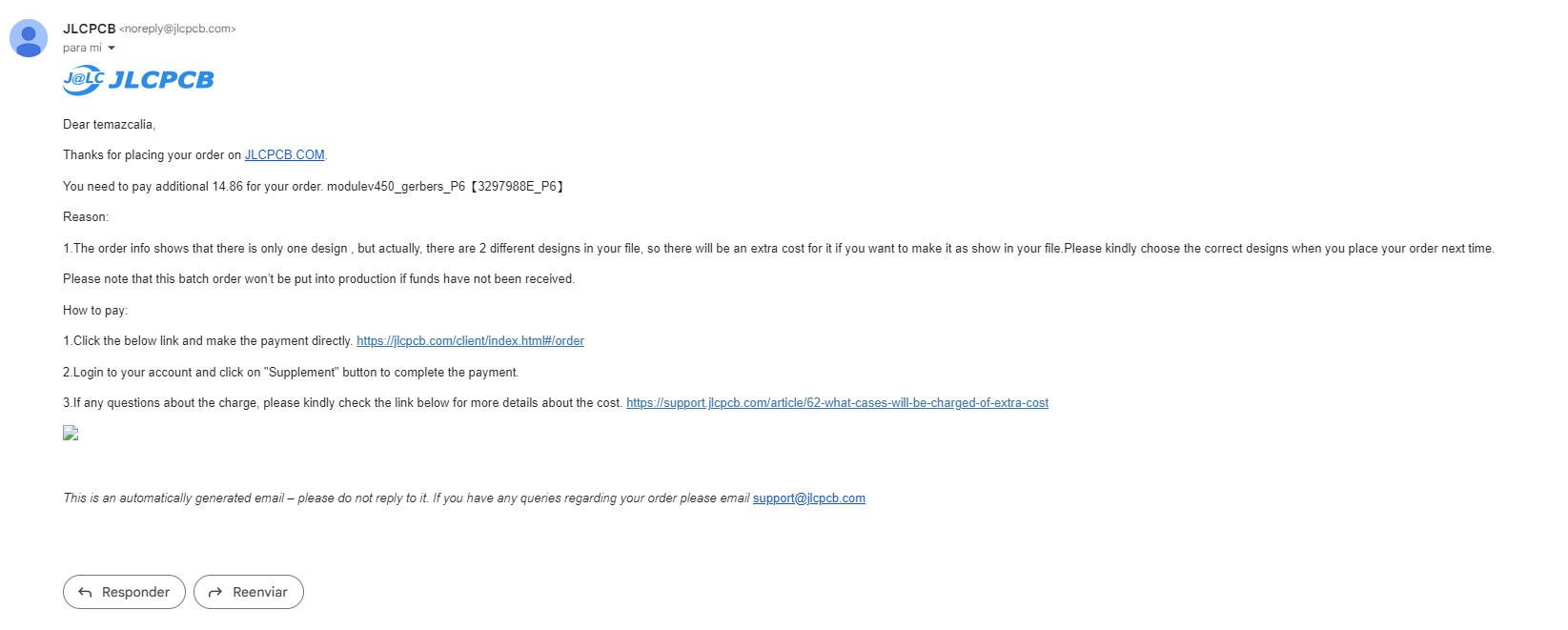
did you see the pcb on jlc website? there was just only one?
Solved, I canceled the order and reordered the boards with the latest version of Stuart’s Gerbes. As for the Attiny, I have ordered them from the manufacturer (Microchip) it seems that they will deliver them to me in 60 days.
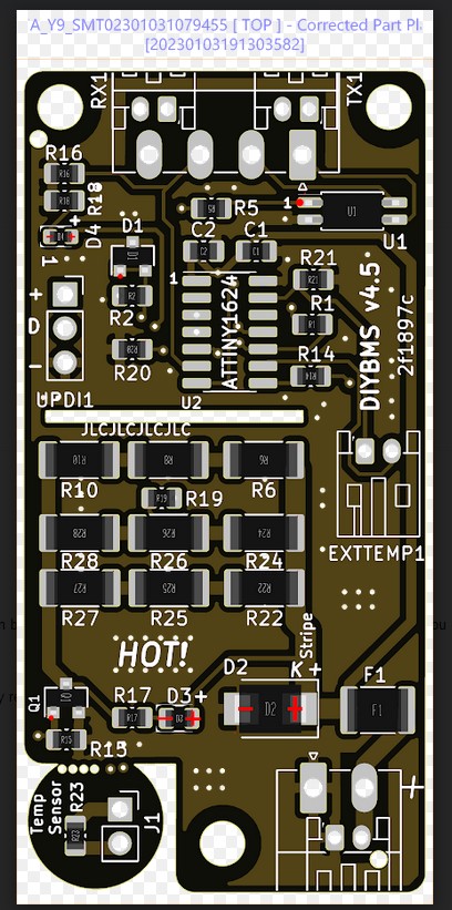
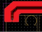
I’ve never been asked about D3 before, but D2 often crops up - they think its a standard DIODE but its a TVS DIODE which confuses them!
On D2, the “stripe” of the part needs to be on the right facing the “+” - however its likely that JLC have the part in their system incorrectly.
Just make sure when the boards arrive you check D2 - and ensure the stripe is where the “stripe” word is on the silkscreen - if its wrong, you will need to unsolder that part and flip it on all the boards.
mkay, thanks