As there’s been some confusion about this part, I’ll explain it in a slightly different way.
The point is that I_CH is calculated iteratively. Given: the previous value of I_CH (start off with zero), a voltage-dependent limit N=(M-H)*I_CH_MAX * 5, a cell-specific maximum I_CH_MAX, and a dynamic value I_CH_TARGET = I_CH+(N-I_CH)*0.1 that essentially means “I_CH moves a little bit towards N”.
With this, you calculate a newI_CH := min(N, I_CH_MAX, I_CH_TARGET), report that to the charge controller, wait a second, repeat. Thus if the voltage rises, I_CH will instantly decrease; if it goes back down, e.g. due to a heavy discharge, I_CH will increase slowly so that there won’t be an even heavier charge that could overwhelm the cell.
The reason I’m doing things this way is that the cells have some internal resistance (what a surprise …). Thus the cell voltage depends on the current going in or out. (And on the cell’s charge level, and the temperature …) Rather than imperfectly modelling the physics of the battery and its cables and whatnot, the idea behind this code is to prevent violent changes that might stress the battery and/or trigger the overvoltage protection.
NB, I’m also doing the same current limit calculation in reverse, limiting discharge current when a cell approaches the lower voltage limit.
NB2, the factor of 0.1 depends on “we calculate this as often as the controller actually reacts to our value”. If you’re on a Victron system where the inverter requires five seconds to start reacting to your changes, you need to set that to 0.02 or thereabouts. Yes this means that the max charge current changes somewhat more slowly than you’d expect, but in this situation the battery is already very full anyway. Avoiding any risk of running the cell voltage into the hard “uh-oh, this is not working, let’s trip the relay” limit is worth a few more seconds before you can resume aggressive top-balancing, which frankly is the only situation any of this should even matter.
I don’t “control the charging”. The beauty of this algorithm is that I don’t even have to think about balancing or whatever. I just tell my system that as soon as the top cell reaches 3.45V this point is defined as 95% SoC; similarly for the lowest cell with 5% at the bottom. The overall charge/discharge strategy code runs every hour and calculates which SoC I should aim for in order to minimize my power cost (or, in summer, maximize my profits).
Of course I still need to top balance sometimes. I do that by looking at the voltage delta between the top and bottom cell at that 95% point. If it is too large I set the upper limit to 98% instead, and then I simply wait until the problem fixes itself.
All of this is a heap of Python scripts which I still need to restructure and package up before they are ready for public consumption. Too much to do and all that.
hi @stuart . Nothing special , I have set my inverter charger end of charge absorption voltage to 55.2V for 1 hour. The current tapering is due to pack voltage approaching 55.2v (Natural taper) . I find my pack of LF280K’s current drops to a few 100ma in about 15 minutes into CV charging at 55.2v . The DIY BMS has a remaining 45 minute window to do its job. 55.2V pack voltage = 3.45V per cell. I learnt balancing lower than 3.45v is not a great idea as you are still in the flat part part of the LiFePo4 charge curve .
if one cell reach maximum set cell voltage the bms set this overall pack voltage as a new voltage limit and send it to the inverter.
so the inverter is throtteling down the charge current and the cell has time to balance.
it would be great if you can implement this in the canbus
Thats very similar to what @Smurfix is suggesting. As a cell nears (or exceeds) the balance voltage, the overall charge voltage is lowered to hold the charge process at that level.
This should enable the cell to then balance as needed. The current automatically falls as a result of the lower charge voltage.
Hi @stuart , in your GitHub repo I sow you are referring “A grid tied inverter would be required to convert the battery DC into mains level AC.” Could you please share have you tested some manufacturers or models of grid inverter we may use? Also
what is your advice for bat. charger from your experience?
Thank you in advance for your comments.
Hello everyone.
I am a very beginner and I wanted to see if you could give me any hint of suitable tutorials or guides to start learning Mqtt, emonCms and InfluxDb. Especially for DIYBMS applications.
I’ve been searching and the truth is that I don’t quite see where to start, with as much documentation as there is.
Thanks and sorry for such a naive question.
Hello,
Is there a list anywhere of additional items need to make the diybmsv4.4 work?
Ie, esp32, jst connectors, header pins etc?
I have ordered boards fully assembled from JLCPCB but also need remaining parts to make them work. I currently in Tunisia for the winter and need to have friends bring items in when they visit and hence the requirement for a list.
Thanks.
Dennis
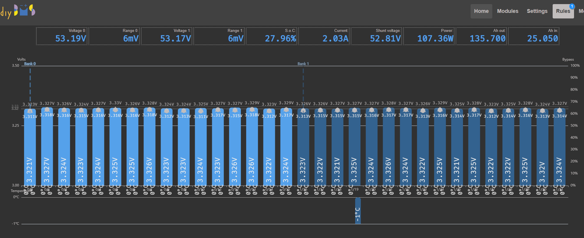
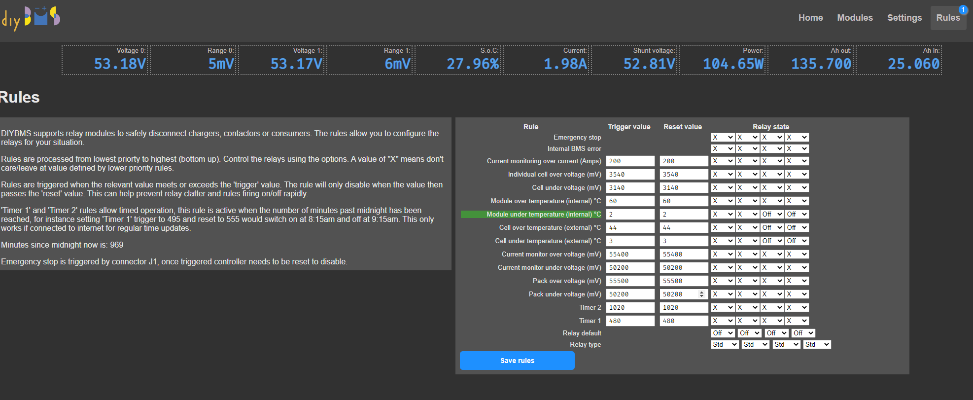
Unexpectedly today the temperature dropped and the sensor detects -1 temp, which is certainly resistant.
The problem is that when the temp cell is less than 0, the rule turns off and the inverter starts charging.
This is a very dangerous condition for my cells, but is this the expected behavior?
When the temperature is above 0 the rule works fine.