LiFePo4 cells have 3.2V all time, without discharge, charge. Not reponsable this to SoC. SOC correctly indicates coulombmeter, - smart shunt, BMV700 etc.
I’m looking for 20 of the V4.4 modules. The site store seems to be out of them. Is there anywhere else that I can get them? or would getting them made in JLCPCB be the best bet with Stuarts links, files and instructions?
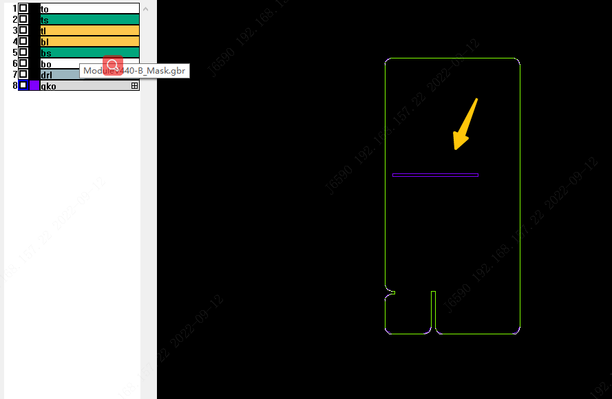
I thought so too! but the support specifically said it was this long V-cut.
I also ordered the identical boards a few weeks ago and there was no issue. I mentioned that to the support, and they said that they will “punish the colleague” because he missed it. WTF.
Has anyone an idea to get an ESP32 with LAN connection work on the controller?
I found one but it seems it is not electrical compatible. Less pins and diffrend configuration.
We have steel beton between the router and the controller.
And we do not want to set a repeater. Cable connection is more reliable.
So I’ve been around here for awhile but I finally got around to working on my setup again and I have a problem with OOS and possibly bad CPU’s. Does anybody know how I can debug this reliably? I have desoldered and installed a lot of new cpus and I almost have an error free board but I’ll get random Oos. Is there debug code that can tell me which module communications stopped at? If communications couldn’t finish its trip?
It’s a unidirectional loop, so no there cannot be any debug code to show where comms stop, at least not when it’s completely broken.
Otherwise, well, you already have per-module packet counters and can infer from them where an intermittent error is located.
I was thinking about implementing like a timer in the code to trip if communications weren’t received in a certain amount of time, then add it to the information on the next comms trip to be recorded in the log. Seem viable?
Well, I’ve got LAN, by way of connecting the optocouplers to a RP2040 and plugging that into a Raspberry Pi (running Victron’s Venus image; no CAN bus required).
Still needs some refinement, as well as a bit of hardware design, before it’s ready for the public. If anybody would like to preview this thing, DM me.
There is no LAN on the RP2040. It’s connected to the host via MicroPython’s built-in USB-serial driver and exchanges msgpack-etized command/status messages with it.
Any web, mqtt, or other front-end stuff is the host computer’s problem. Right now I’m even tunneling the serial messages to the cell modules to the host and process them there, because debugging that code is a lot easier on a “real” computer; obviously that’s on my “fixme ASAP” list. As is connecting a better ADC setup (i.e. less noisy and less input current) than the RP2040’s built-in one, for voltage and current measurement.
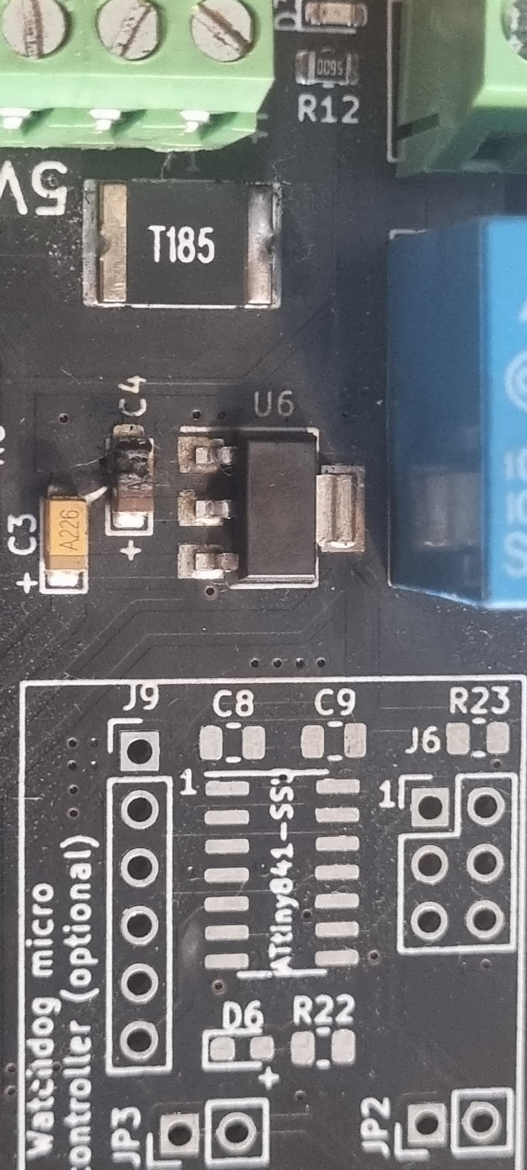
Damn…just when I touched up my crappy handsoldering with a proper soldering station from my son…i managed to let the magic smoke come out of capacitor c4 on my controller board. I obtained some 4.4 boards which had allready been assembled bar the attiny’s. I had the communication leads attached to 1 module before i attached the battery connection (@3.86v) all other components seem ok, do you guys think it ok to just solder in a new c4 component?
I have had no luck programming a shunt yet…i have a arduino uno connected to my laptop and connected to the shunt. But i no succes yet, tomorrow I try again
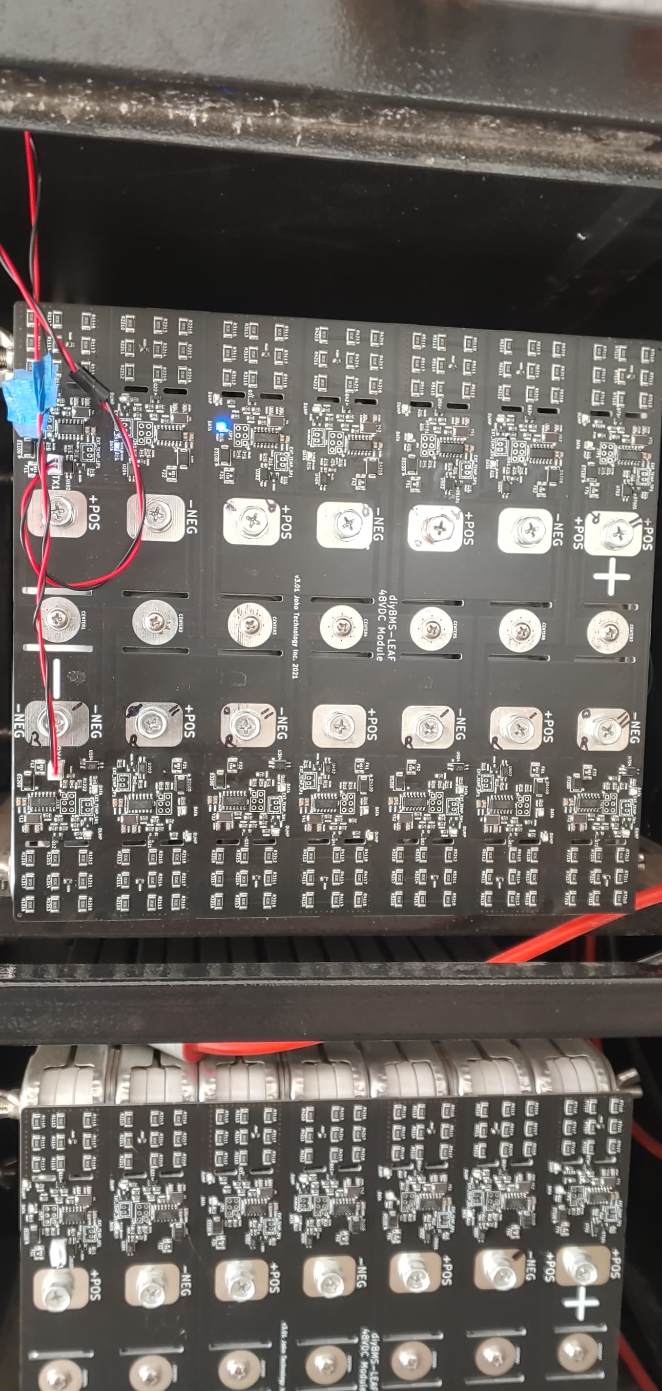
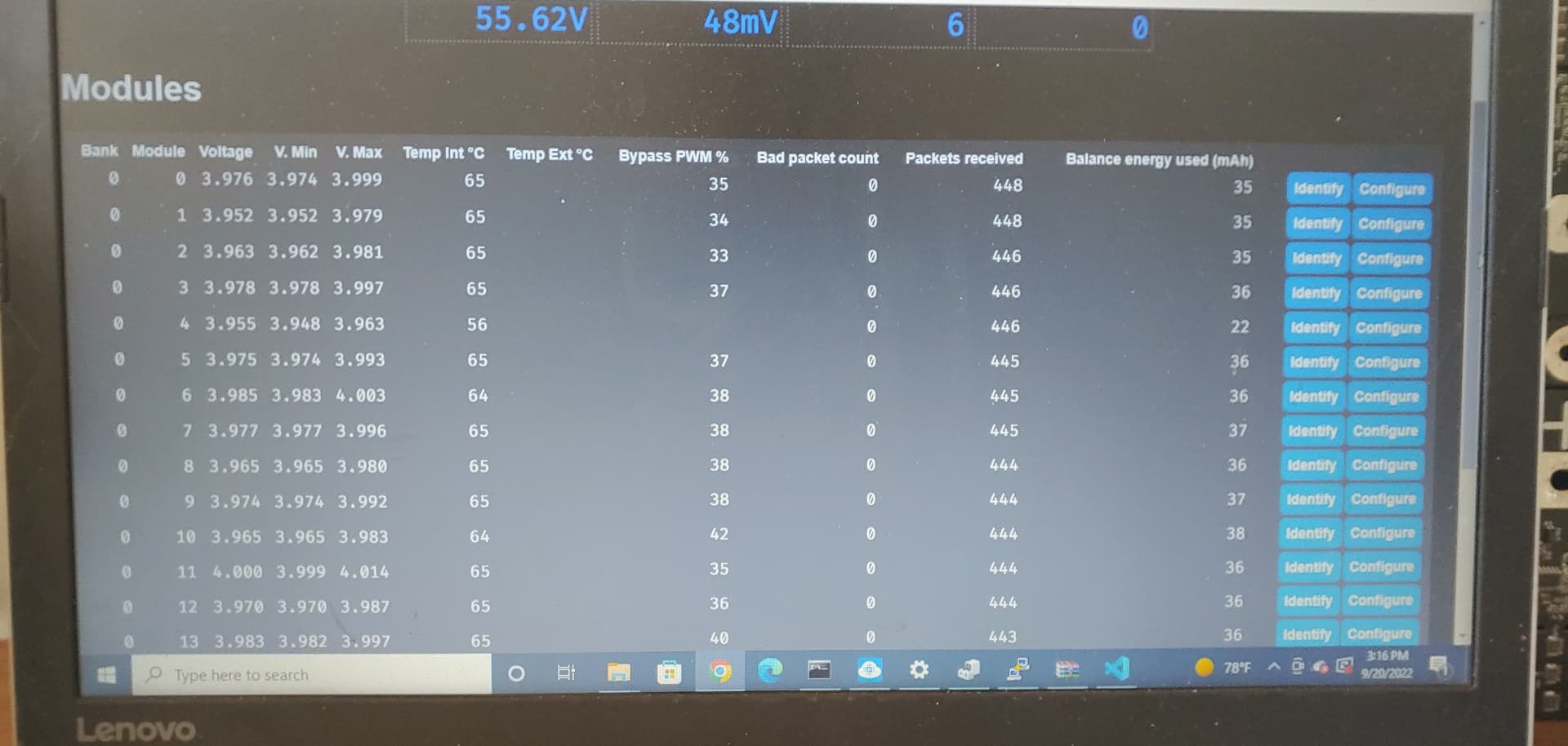
I just found I get a lot more info on the PC browser than my phone. What can you tell from this? #2 I have installed a new CPU and a different optoisolator, same kind just from another board. These oos and crc mainly happen when the board is in bypass. And when I say #2 I mean physical #2 so #1 in the Pic, it wasnt passing the packets from #1 to #2 but after the new CPU it seems to pass them along but still losing packets. I am using these boards created by Allan Lind who tells me his are working flawlessly.