Thank you very much.
I do not control much of the subject, but it is time to learn.
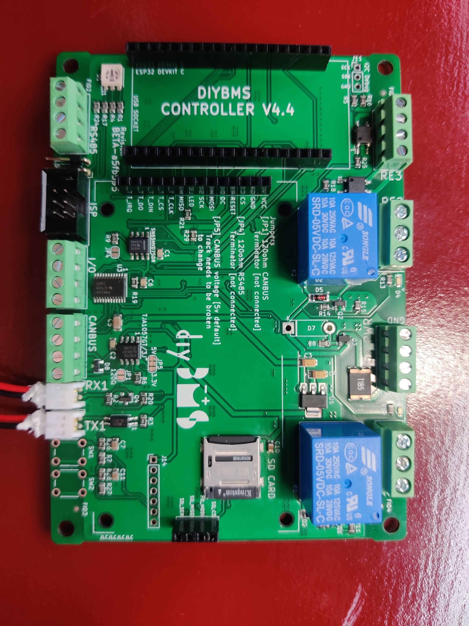
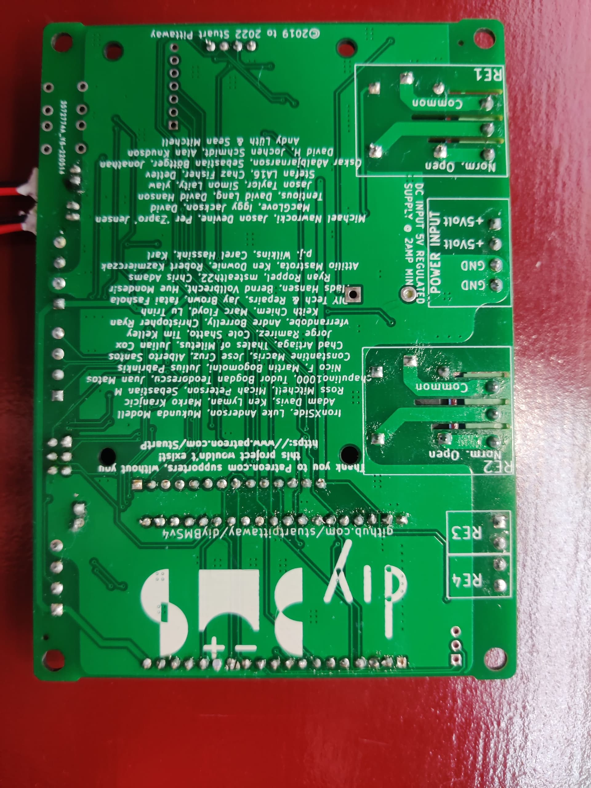
As far as I see the screen is correct. I don’t know what the touch IC is, but from the photos of the bangood I don’t see anything missing. I attach photos of my screen.
The message I get when opening a session with Putty is the following:
CONTROLLER - ver:4738cb2d9b1e73596022ae7c18804b59e644aa37 compiled 2022-05-13T08                                                                                                                                                                             :58:50.073Z
ESP32 Chip model = 1, Rev 1, Cores=2, Features=50
I (41) diybms-hal: Configure I2C
I (44) diybms-hal: Scanning i2c bus
I (49) diybms-hal: Found i2c device at address 0x21
I (59) diybms-hal: Found TCA6416A
D (60) diybms: Configure VSPI
I (61) diybms: ** Controller changed state from Unknown to PowerUp **
I (63) diybms-hal: CAN driver installed.  Filter=1621098496 Mask=6291455
I (69) diybms-hal: CAN driver started
I (85) diybms: LittleFS mounted, total=589824, used=98304
I (185) diybms: Mounting SD card
[   691][W][sd_diskio.cpp:104] sdWait(): Wait Failed
[   691][W][sd_diskio.cpp:512] ff_sd_initialize(): sdWait fail ignored, card ini                                                                                                                                                                             tialize continues
[   693][W][sd_diskio.cpp:516] ff_sd_initialize(): GO_IDLE_STATE failed
[   699][E][sd_diskio.cpp:802] sdcard_mount(): f_mount failed: (3) The physical                                                                                                                                                                              drive cannot work
[  1208][W][sd_diskio.cpp:104] sdWait(): Wait Failed
[  1208][E][sd_diskio.cpp:126] sdSelectCard(): Select Failed
E (1204) diybms: Card mount failed

[  6216][D][settings.cpp:23] ReadConfig(): [diybms-set] ReadConfig diybmswifi
[  6219][D][settings.cpp:45] ReadConfig(): [diybms-set] checksum verified
I (6217) diybms: Fetch config
[  6223][D][settings.cpp:23] ReadConfig(): [diybms-set] ReadConfig diybms
[  6235][D][settings.cpp:45] ReadConfig(): [diybms-set] checksum verified
D (6234) diybms: Setup RS485
D (6236) diybms: Configure RS485
I (6240) diybms: ** Controller changed state from PowerUp to Stabilizing **
D (6245) diybms: starting wifi_init_sta
I (6266) diybms: WIFI SSID: Red_Ppal
D (6302) diybms: tca6416a_isr
I (6364) diybms: Hostname: DIYBMS-00D204B8
D (6365) diybms: wifi_init_sta finished
*I (6365) diybms: TFT screen is NOT installed*
D (6365) diybms: total_free_byte=182520 total_allocated_byte=113220 largest_free_blk=110580 min_free_byte=182172 alloc_blk=316 free_blk=5 total_blk=321
I (16360) diybms: Got ip:192.168.1.87
I (16362) diybms: Request time from time.google.com
I (16362) diybms: Timezone=UTC0DST0
I (16364) diybms: The current date/time is: Thu Jan  1 00:00:07 1970
I (16389) diybms: You can access DIYBMS interface at http://DIYBMS-00D204B8.local or http://192.168.1.87

D (75203) diybms: total_free_byte=165120 total_allocated_byte=129576 largest_fre                                                                                                                                                                             e_blk=110580 min_free_byte=160820 alloc_blk=403 free_blk=10 total_blk=413
I (75249) diybms-rules: Set error 4
I (75250) diybms: Active errors=1
E (75294) diybms: Packet Failed
E (76194) diybms: Packet Failed
I (78250) diybms-rules: Set error 4
I (78250) diybms: Active errors=1
I (80073) diybms: Task 2
I (81251) diybms-rules: Set error 4
I (81251) diybms: Active errors=1
E (81294) diybms: Packet Failed
E (82194) diybms: Packet Failed
I (84252) diybms-rules: Set error 4
I (84253) diybms: Active errors=1
I (86573) diybms: Task 3, s=0 e=0
E (86787) diybms: Packet Failed
I (87253) diybms-rules: Set error 4
I (87253) diybms: Active errors=1
E (87687) diybms: Packet Failed
E (88587) diybms: Packet Failed
E (89490) diybms: Packet Failed
For reference, on the TFT LCD back side U2 is the touch IC. If that is not present the diyBMS code will NOT detect the presence of the display (though it may initialize and use it during startup it will shut off soon thereafter).
Glad that you have sorted the issue out with the MOSI pin!
When I run DRC on the 8266controller and the V4.21 cell modules on KiCad, it shows multiple courtyard overlap errors. I also sent the designs to FreeDFM and it shows some Missing Soldermask Clearance violations. I don’t have much experience in PCB development. Are these errors important or can I order the PCBs using these files?
I made some changes just on the silkscreen by adding some text. Both the original gerbers by Stuart and the new gerbers show these results.
The 8266 controller is an older design and has not been updated for a few years now. I recommend not using that if you are planning to build a new setup.
As regards to the clearance violations, I’m not sure, KiCAD was used to generate the designs, and it passes the internal checks in that tool. The circuits have been built using the Gerbers supplied without issue.
Can I ask why you need to add new text to the silkscreen?
Hi all, I’m new to forum
I’ve made two boards with ESP32, they are working with 4.40 modules. I had some problems with parts availability, so I used TCA9554DW and made address changes in code.
I had some issues with logs on SD Card and time settings. I suppose my firewall settings are blocking acces to NTP servers. I’ve checked on ohter internet connection and it works fine.
I have suggestion to add time settings option in web interface if are problems with NTP connections.
Without correct time settings logs to SD cards is unavailable.
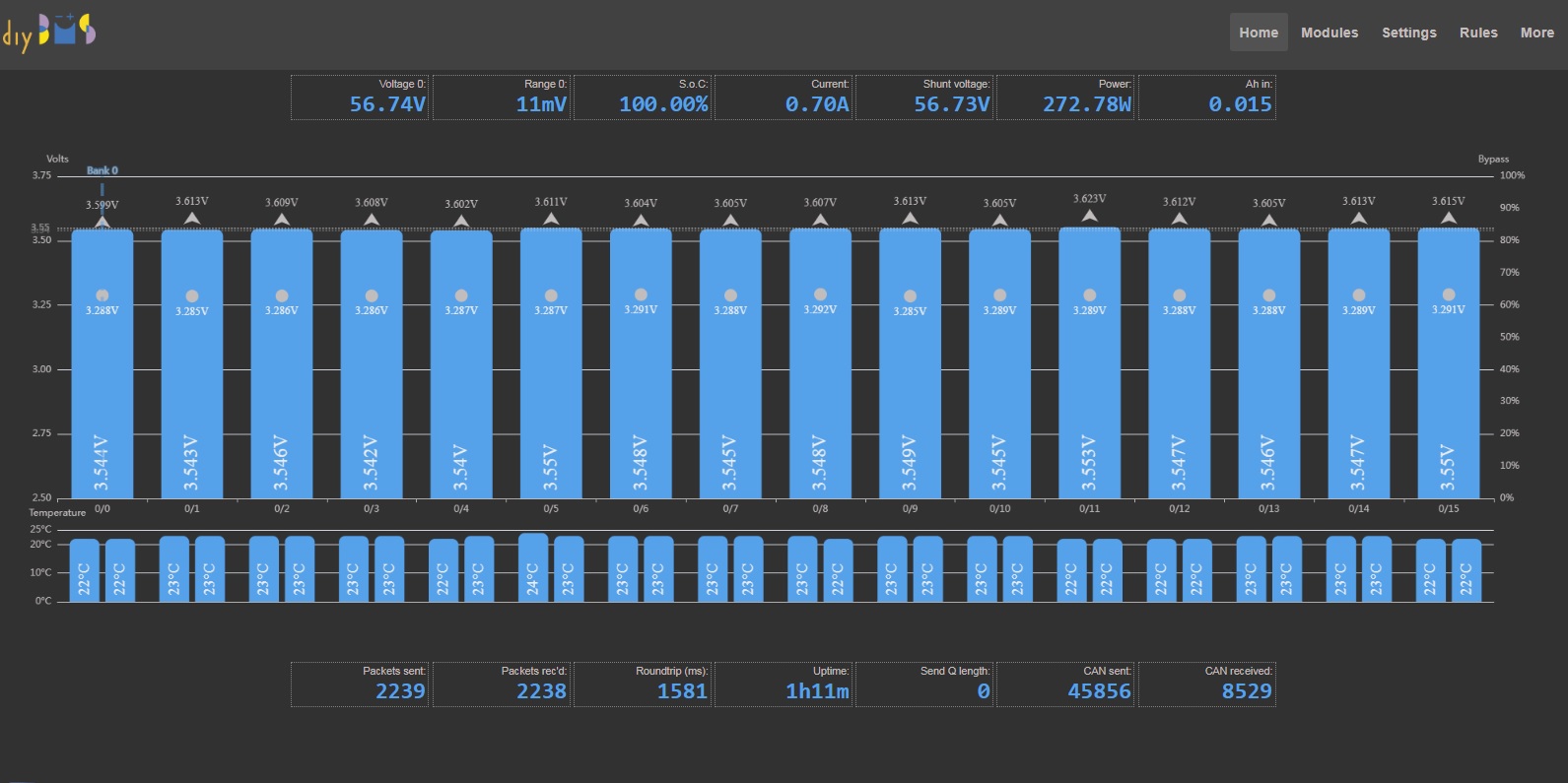
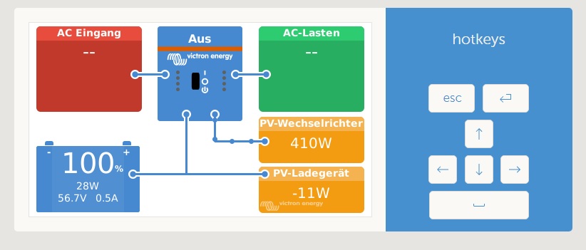
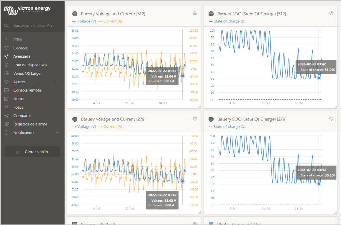
in my humble opinion these small differences are not significant. here you can see the readings of DIYBMS (512) and those of the Victron Shunt (279) in my system
You must also take into account the temporary differences between the readings of one and the other, you are with a very small load that may be being read at different times in one system and the other.
A few people have reported issues with the shunt power reading. This value is taken directly from the chip in the shunt, so should be accurate, but appears not!
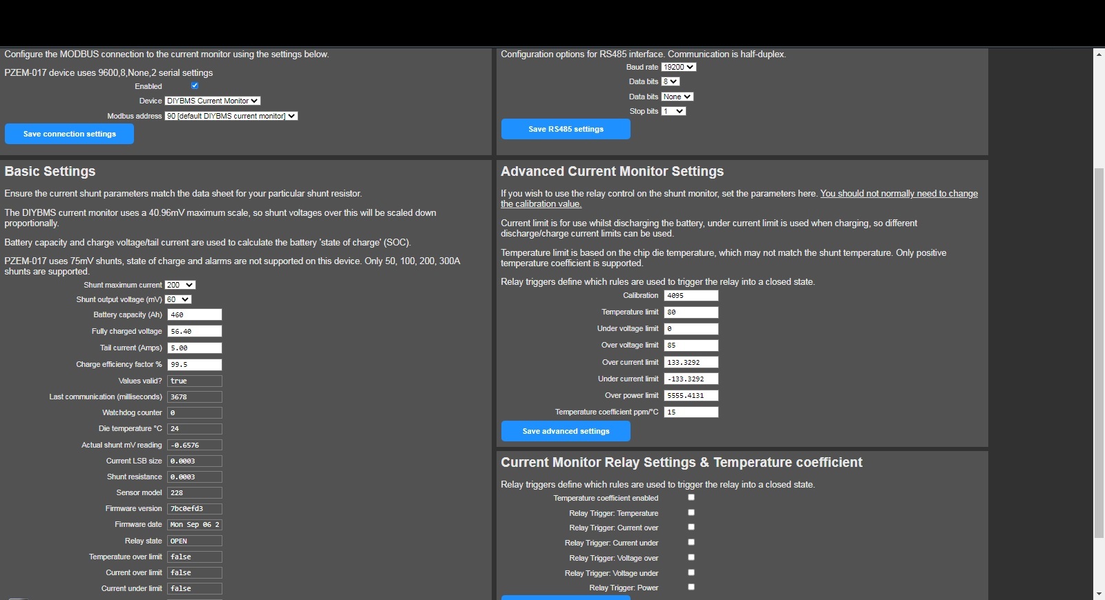
i have noticed another bug if the shunt mV reading is over 30mV it displays wrong data
i have a shunt 200A 60mV and on 30mV i have exactly 100A if i go over 30mV and 100A it display sometimes 60A or less total wrong numbers and over 30mV the reading in the shunt pcb is inacurate
so to solve this problem i ordered a 500A 50mV shunt because i need 300A so 30mV would be enough
@stuart
NOW THE GOOD NEWS
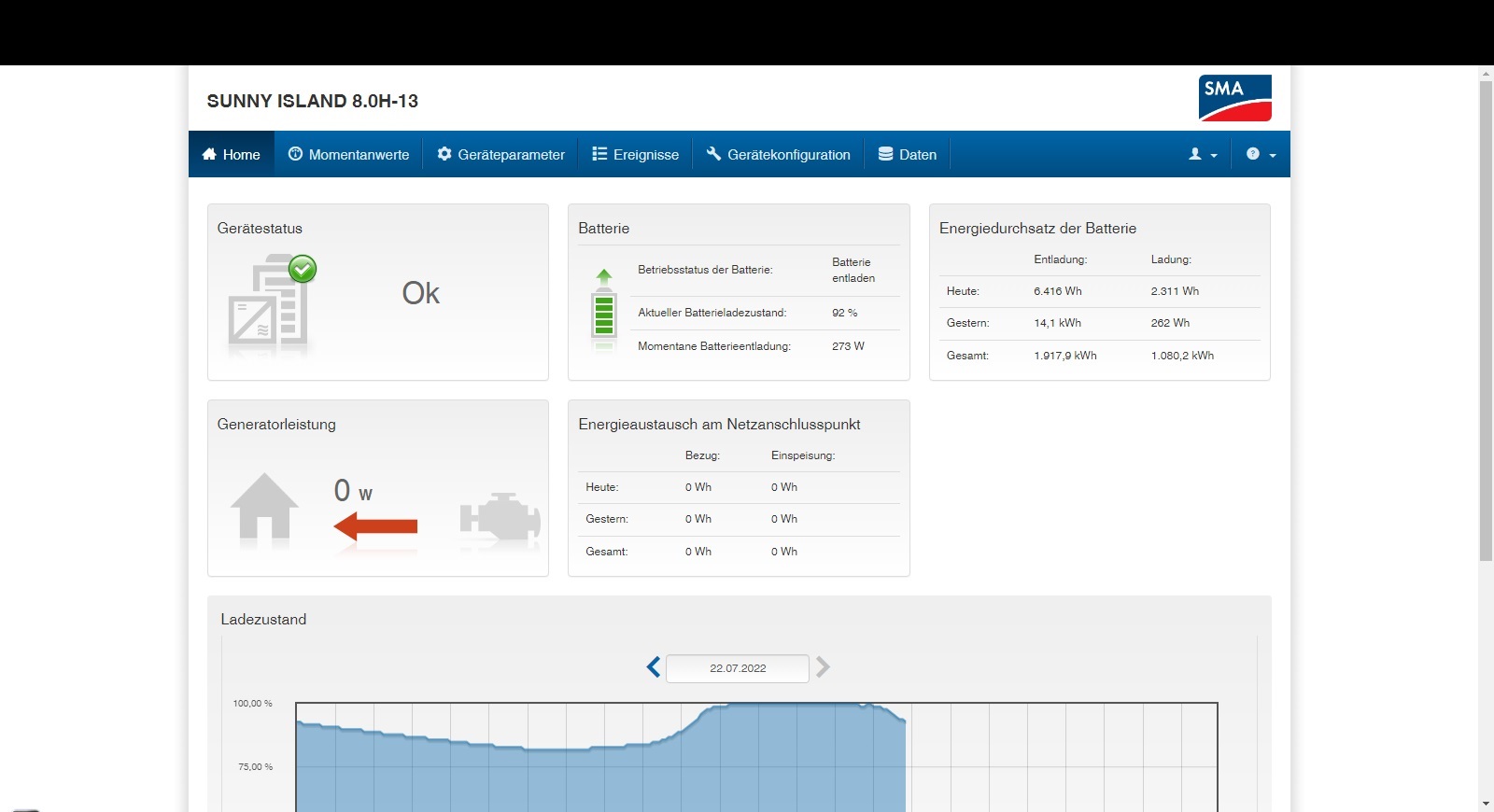
it is working with my sunny island 8.0h-13 THIS IS AWESOME
but cant be mixed with victron dvcc because the charge voltage need to be 1v higher its a sunny island thing
if i set 57V the charge voltage in sunny island is 56V but 57V on Victron
Any chance you can share your sketch? I am trying to use the KG-F to test and record the voltage and current on a small cell test station I am using to test cells for an EV conversion…
EDIT:I Saw now that you attached it above… Thank you!