
current from R20 1Mohm is very low (3uA), place this about 1-10k for current from Q4 about 1mA.
It should work as you describe.
what do you mean? you saying to replace the r20 1m ohm to a 1-10k ohm?
R20 at 1 MOhm is probably too high, given the capacitance of the transistor and the input pin (~100pF).
Replacing R20 with ~2kOhm however would cause a battery drain of ~2mA at all times. You definitely don’t want that. (Or at least I wouldn’t want that!)
What exactly happens that you need this transistor anyway? Would reversing the polarity of the serial signal (so that it’s active low) also solve this problem? (That’d be difficult to apply to an already-populated board because pin 2 of U2 is tied to ground. That would have to be replaced with pin 1 being tied to Vcc.)
@Smurfix the background for this change was in this thread.
A lot of people have no issue with communication data being lost, others have had lots of problems. Most of the issues appear to be EMI style noise, others are different brands of inverters or the routing of data cables near power cables etc.
Most of the data comms issues appear to be between the last module and the controller (the RX line) therefore, a change was suggested as below. The change only costs a few pennies in parts, so seems reasonable if others have seen a benefit.
Ah. Thanks, I missed that.
I can immediately think of a much easier fix, which is not to have a long last-cell-to-controller cable in the first place. Thus instead of connecting your modules C-1-2-…-15-16-C you link them C-1-3-5-…-15-16-14-12-…-4-2-C. (Adjusted for however many cells your battery has of course.)
Yes this means that the nice blinkenlight trail from the first to the last cell doesn’t look all that nice any more ![]()
Yep, cable length is normally the first suggestion, alas not always so easy to do in real life.
Anyone got spare v4.4 controller and shunt, and moduels.
I am basically the only.person in South Africa using the original BiyBMS and I have just expanded my powerwall from 14cells to 42cells.
Getting boards made and shipped to us is a real PITA. I have a friend gong to the UK in June so getting it to me from there is not a problem
Thanks in advance
Stuart Pittaway and all others involved building the latest code for the controller, a huge thank you, 4,5 days after upgrading and so far no more spontaneous reboots ![]()
![]()
@stuart and others,
can I use MQTT to change Controller relay states?
as in pulse RE1 to turn my contactor off and then send a pulse to RE2 to turn my contactor back on?
haven’t messed with this protocol yet, so before I start spending time on it, are relay states “exportable” or whatever the term is?
cheers
V.
MQTT is outbound only from the BMS. It does not listen for incoming messages.
thanks Mike,
I guess there wouldn’t be any easy way or other reason to implement an inbound stream to it?
so the only way would be for me to use the InputA/B/C/D to “inform” Controller of my intentions. Then goes back to issue #121 on github re new rules/ways to get a bank offline and online again via pulse signals.
V.
It is likely feasible but I don’t know how it might impact other parts of the system. The question might be under what use cases should the BMS consider inputs from MQTT, what should be configurable/toggleable via MQTT etc.
well I could think of a few ![]()
-
change rule sets (call them profiles if you wish) from say full use to idle/storage operation: For example on a boat when in use I’d like to take advantage of the lifepo4 capacity in the summer season, but would like to run them at 40-50% SOC and loop that during winter. Well I guess the main issue here is that atm we cannot have different rulesets. Actually would be nice to have a couple of presets like 18650 and lifepo4, as currently when I load a new setup it’s default values are 18650 tuned. Actually I’ll post profiles in rules now in github I think it’s a worthy inclusion!
-
manage banks (or as in my case, get lifepo4 offline to “exercise” the FLA Trojans that are running in parallel and would like to get them up to 29V once in a while)
-
operate pulse toggling on BlueSea contactors

cheers
V.
- I’m on the newest build (esp32) but can’t save the rules. All other settings save and the diyBMS seems to be working otherwise perfectly. One post recommended different browsers but that didn’t help.
- Also when the wifi settings are saved (it says saved), I’m not seeing a file on the sd for that (all other files appear).
Thirdly, I’m using Leaf cells - does anyone have recommendations for the settings? I’m running 14S (6packs per) and trying to go for longevity.
Hello @MasMat
-
Can you tell me what happens when you click save rules, message on screen? If you look at the console output for the controller, any messages
-
DIYBMS Storage won’t show the wifi.json file - its hidden on purpose
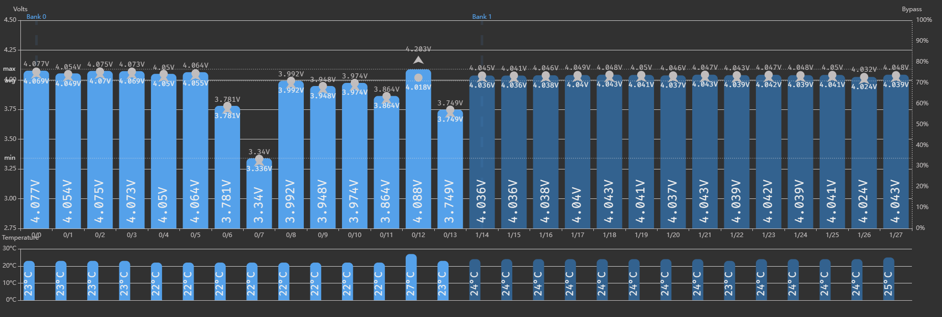
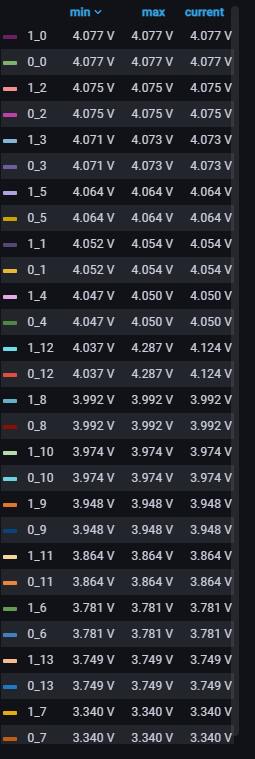
@stuart there seems to be an issue with the controller and sending data influxdb is posting data incorrectly,
I have 14s2p configuration and I have set the controller to send data to influx however it seems that the info for the first 1s is duplicated for 2s rather than the 2nd bank having it’s won readings.


Ok, what version of the software are you using? I think this was a known bug but fixed quite a while ago.
Version: 87f6de125b10ed8b0e9e4830e15a79ecb33127d8
Compiled: 2021-10-14T09:14:37.098Z