Ok, you should have them on bank zero and bank 1 not 1 and 2.
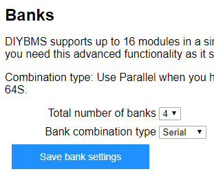
Try changing the number of banks option to 4 so the other modules appear
Ok, you should have them on bank zero and bank 1 not 1 and 2.
Try changing the number of banks option to 4 so the other modules appear
It looks like it did not help.
Thank you
Ok, this is strange as it should show all the modules in the string perhaps there are more than 16 in the same bank now and that’s causing an error.
I’d suggest reprogramming some of the attiny modules to clear the flash and get them working again.
Can you recommend please way forward?
How is it intended to assemble such setup?
I can re-flash all of them to get all of them straight, and than what?
Connect 4 of them and switch them to bank1?
Than connect rest and keep them in bank0?
At which point should I put in settings that I have 2 banks in series?
Can you point what is good path to follow it?
Thank you
First up, connect only 4 modules. Move these to bank 1. Now add 16 modules and leave them on bank 0.
Set the number of banks to 2 and series mode.
Hello Stuart,
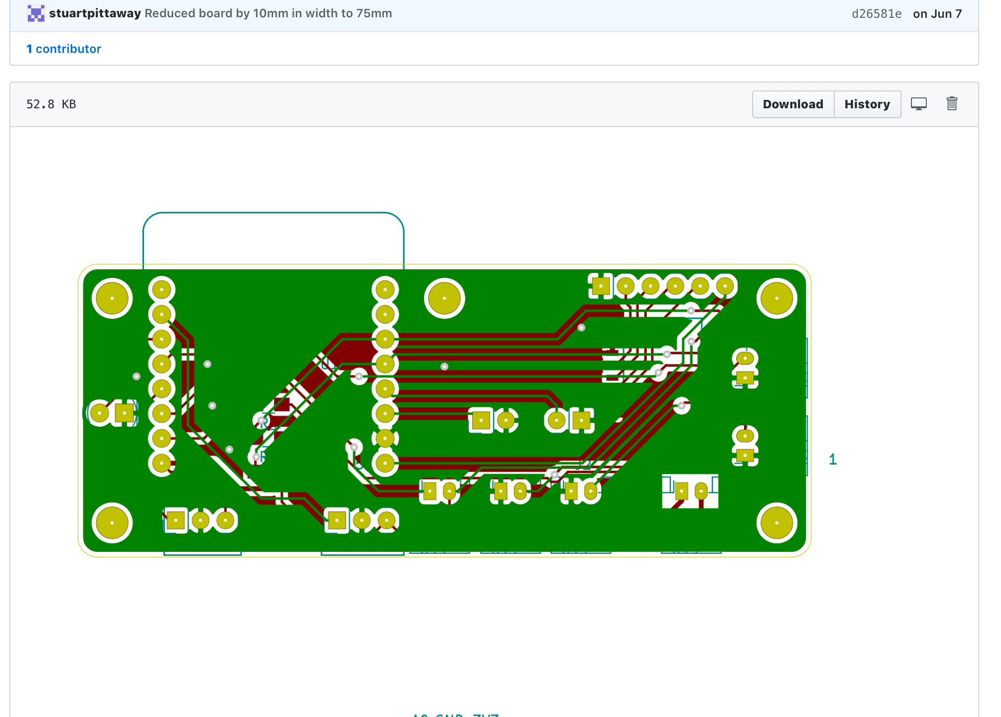
I am going to build v4 using Your gerber files and components lists provided at github. Unfortunately I can’t find EspController schematic diagram at github. Is it available to obtain ?
Rgds
Its in GITHUB - take a look in the ESPControllerCircuit folder
https://github.com/stuartpittaway/diyBMSv4/tree/master/ESPControllerCircuit
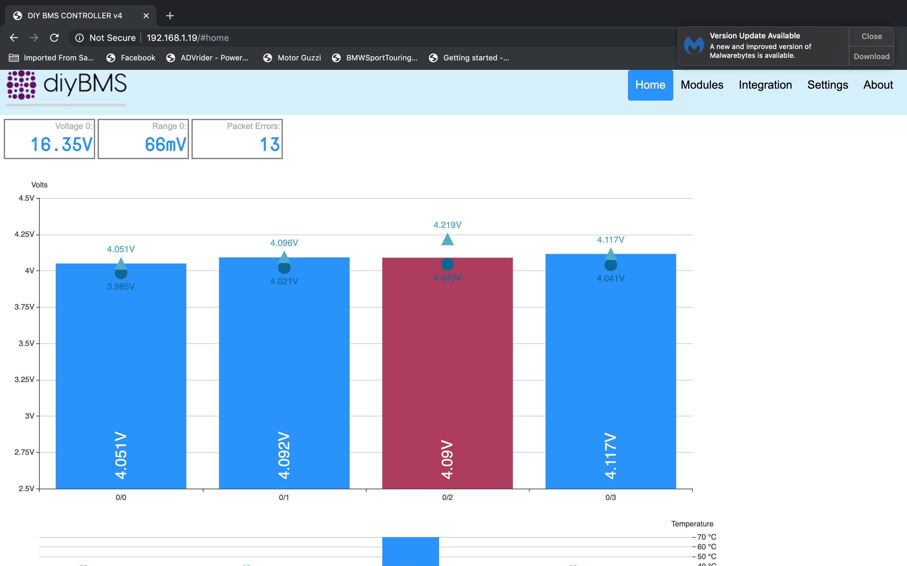
My 14s80p is pretty close and needs no balancing at this point. Max = 4.17 and Min = 4.11.
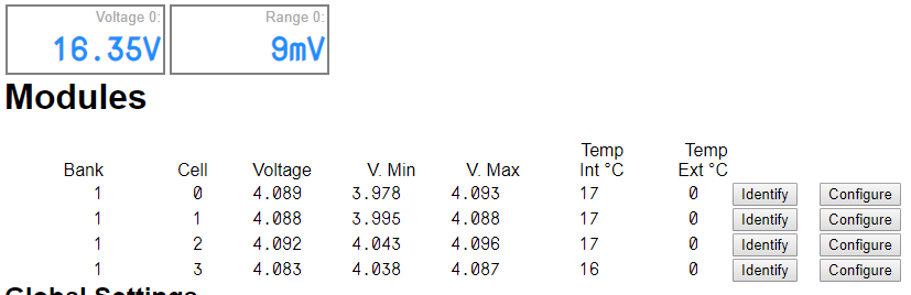
I have 4 modules connected. All 4 have blinking red lights (bypass and 70c). Makes no difference if the controller is on or off.
Voltages are off from actual: 1 = 4.11, 2 = 4.15, 3 = 4.16, 4 = 4.17, and don’t seem to take my corrections in calibrate?
P.S. I was unable to post to V4 Hardware thread, as I have exceeded my 3 post allowed and was too old to edit a previous post.
Dave,
I bumped your user level up a notch, so that shouldn’t be an issue any longer.
Thank you sir.
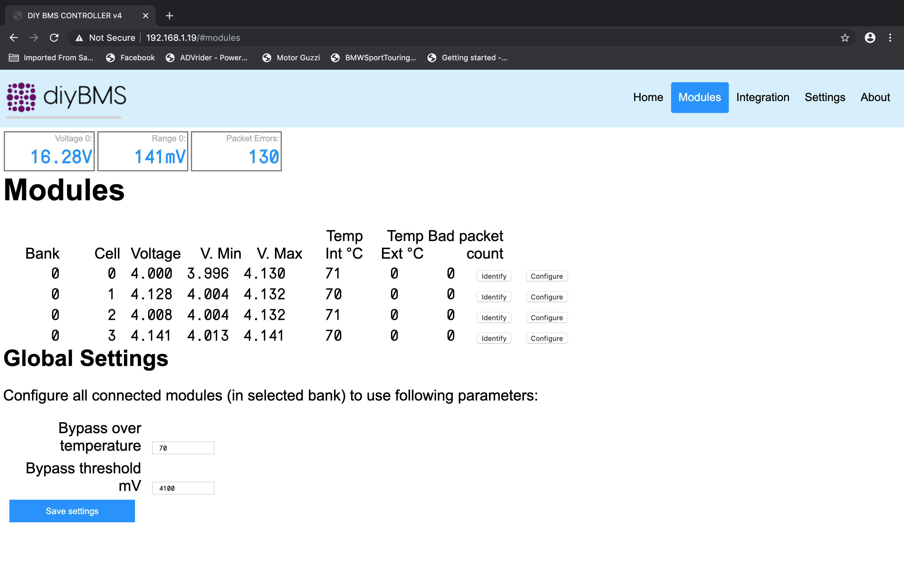
Hello @Tiger_One some of the modules will be in bypass because the calculated voltage is over 4100mV.
You need to calibrate the voltage readings using a multimeter.
Step 1 - Set the bypass voltage to 4500mV (use the global config button to set all modules with 1 click)
Step 2 - After a few seconds the red led should go out on all modules, leave them to cool down
Step 3 - Measure each voltage and calibrate the module using a multimeter (see the YouTube videos for info if you need help)
Step 4 - Set the bypass voltage to what you need.
Hello @stuart yep, I posted too quick, darn it. After a while I thought about it and changed to 4180 and they quit bypassing for the most part.
#3 voltage jumps from 4170 (calibrated) to 4310, so it still bypasses. Temps are all good tho, never got over 72c on any of the 4. I tried another module on #3, same voltages? Wonder if a weak solder joint to the buss bar on my power lead could do that?
Thanks for your support!
You won’t get a reliable voltage reading whilst and charging, load or balancing is in progress as they all drag the cell voltages down (or up for charging).
You are charging the 18650 cells to quite a high voltage - I wouldn’t go above 4.0V if you want them to last.
The Sol-Ark is configured to float 56.5, absorption 56, equalization 55.5. Not sure why it charges to 58.1 or so. I can adjust to try and hit 4.1 which would be 57.4 total voltage.
The lowest Sol-Ark allows is 43v cutoff and 45v start.
The bypassing and eratic voltage was under static conditions, battery offline from Sol-Arc (charge controller/Inverter). When I expect sun next day, I turn grid off for transfer circuits (10 circuits) and go on battery for 12 hours 8pm to about 8am when the PV starts to take over. Batteries are charged by 12 noon.
Are you looking at using the relays on DIYBMS to drive anything or even cut off the charging system?
No, my inverter/charger is completely configurable. I may change my mind in the future tho.
#3 still showing V.max of 4.19 so stays in bypass.
PV is starting to bring the cells up from 4.02v, so a good time to watch the bypassing.
P.S. The Sol-Ark has can-bus, so maybe instead of relay I could send cutoff or battery offline so the grid would not attempt to charge my batteries while I was out of house.
Okay, scratch the Global save not working, I was using a galaxy notebook, now on MacBook pro safari, it works as intended. Also the calibrate sets as intended. Whew, was getting pretty confused while working on the galaxy note.
I’ve had report of another user having trouble on Samsung phone device - is there any error messages you get ?
There are plenty of input/output ports left on the ESP controller so adding some CAN bus commands could be a future possibility.