If you open the project in kicad you can view the schematic in there
Hello,
So, I have tried what you have said - and failed.
First I have re-flashed 4 modules that I have previously put to bank1. Connected just them, and I saw them already on bank1 (re-flashing did not clear setting I suppose) on web interface.
Than I have tried to connect all of them - not single one detected. Even after I have reset nodemcu, waited for 10 minutes…
Than I have removed 4 from bank1, still nothing.
Attached first 10 - they showed up in bank0. Added additional 2 - showed 12 in bank0.
Than I was adding 1 by 1 and conclusion was that it does not work with 16 in one bank, but with 15.
when I removed 16th, it was showing ok, but adding last one - did not show any of them.
After I have switched 16th to bank1, and even adding rest of them, it started working ok.
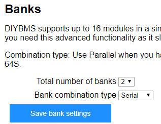
Here is how it looks now:
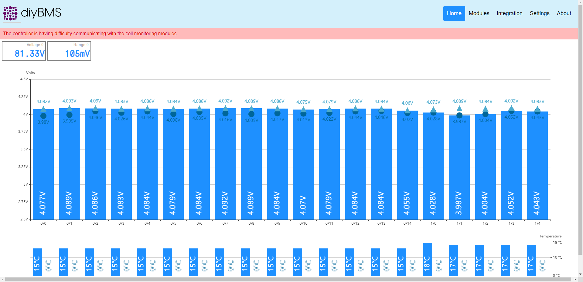
And this is with:
So, to me it does not work with 16 modules in bank0, and even when it works now, I still get error on top.
Do you have some idea what to try next?
Thx
No errors that I noticed, when hitting the global save, I could see the button boundary change color, but on checking the settings in each cell, no changes saved.
Yep, I used a ESP32 (initially arduino nano) for my dual axis tracker (12 327watt panels). So can program a little, but looks caveman style compared to your code.
Thanks for the feedback @Marko_Kranjcic that looks like a bug to me, I’ll try and take a look tonight.
Just for information, if you run with 15 modules and “total number of banks” set to 1 does the error message go away?
The error message appears when a reply from the modules doesn’t arrive within 2 counts (about 1 second). I think this error is actually reported incorrectly as its possible the reads against so many modules takes longer than 1 second.
Are the temperature and voltage values changing when the error message is on screen? (Try putting your finger over one of the temperature sensors to test)
Do you have any way to connect a serial port (FTDI cable for instance?) to the DEBUG connector on the controller PCB ?
Hi,
I will check for this red error message. It is not on all the time. I will try to count “rounds” of packages, when it is ok, and when it turns red.
Regadring to 15 modules - if I remember correctly - I did not get red message. I will re-check this also.
I will also check changing of voltage and temp. If I remember correctly - it changes.
On NodeMCU, I have USB aldready onboard. I did not connect some additional parts with nodemcu. I plan to connect relays but at moment I am focused on making this working. I will try to connect serial port, what is baud rate on debug?
So far I did not have time to check code for modules/controller. I plan to check it also, to see why is there limit on 16 devices in serial, and to see how to improve this.
I really like this project, and I will try to support it more.
Thank you for help
@Marko_Kranjcic the debug serial port is Serial1 - this is transmit only on ESP8266 PIN 2.
Connect this to the RX input on a TTL to USB interface to see the debug messages.
Its 115200 baud (8/none)
Excellent, will do…
Do you have some skype or other account so we can make debug session? or want to post all here?
@Marko_Kranjcic - I’ve fixed the issue, there was a variable overflow issue that I’ve resolved.
16 modules in a single bank works correctly now.
You will need to download and compile the latest GITHUB code and program both the controller and each of the modules
Do I need do this also (download and recompile), I am attempting to connect 12 of my 14 modules today.
Or, will PlatformIO download the updates automatically when compiling? I’m new to Platformio.
Guess not, as mine is working with 12 modules connected. Had to walk over 2 modules at a time for them to populate the console screen.
P.S. Waiting on the 2R2 1watt resistors as I only ordered 100, needed 112 for 14 modules.
Hello i dont know platformio, exist a tutorial for using this?, or *.hex for direct load code to attiny (esp8266)?
Hello @kodl1 I used this video, but I had already installed VScode and PlatformIO, just needed some help compiling.
For the precompiled binary files:
https://github.com/stuartpittaway/diyBMSv4/releases/tag/LatestFirmware
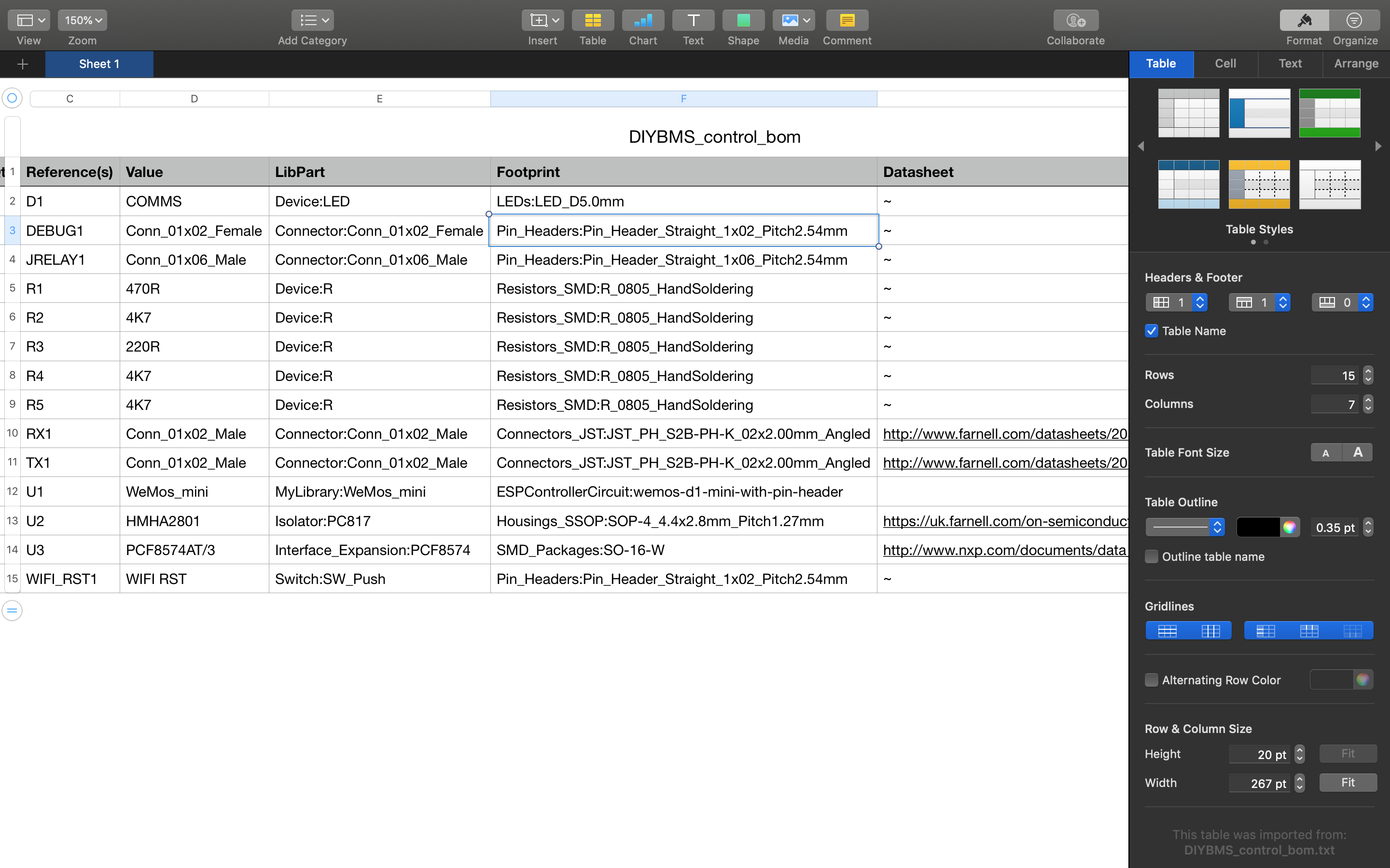
Control BOM:
precompiled binaries is good for me first hardware testing…
Next i need *.pdf schematic connection wemos d1 to optocoupler and PCF8574, i dont have kicad, only cadsoft eagle…
Thanks
Its free - you can download and install it
You can take the update but 12 modules should work fine - it was only when 16 were in a bank that problems started.
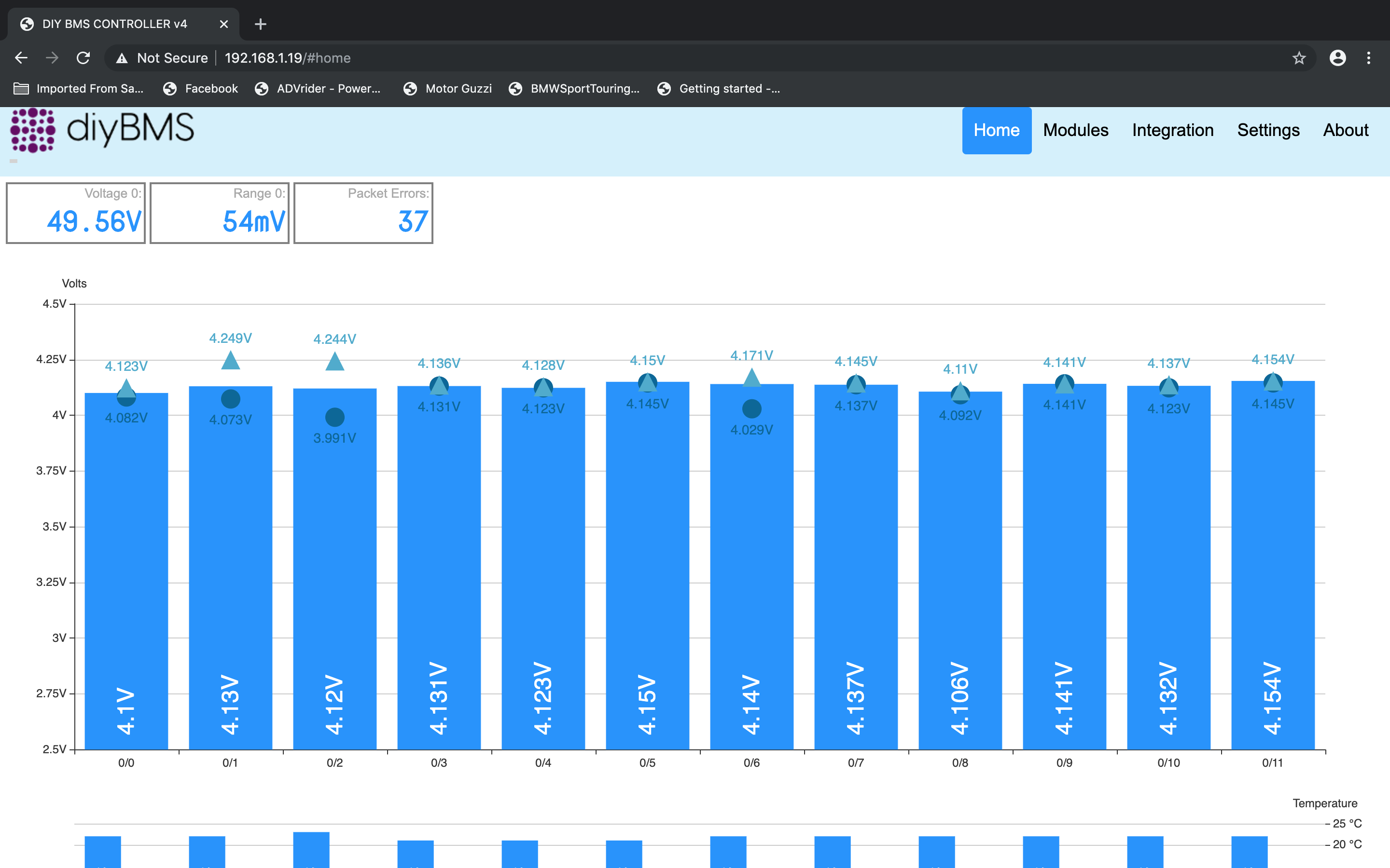
Hello @stuart ran a test last night (9 hours), my #0 cell has always been .04 - .05 volts low compared to rest of the pack.
Started 4.15v - 4.13v for cells #1 - #11 and #0 4.10v
After 9 hours, #1 - #11 are mostly 4.14v or 4.13v, and the weak cell #0 is 4.12v. I set the global bypass threshold to 4.14v before test.
I would call that a successful balance! Great work!
Also, I watched the cells on the monitor while I did a short discharge to 4.08v and checked them with a VOM, spot on for the monitor! This baby works as intended!
Excellent work @Tiger_One
Thanks stuart, that work for me perfectly!
Okay, after you updated the code, this is working too! Thanks al lot!
hi
i hope you code really help me about the modifying the bms4.0 for different types of battery.
i am having battery where nominal voltage is lower the the lithium ion.
having battery like 1.5v to 2.8v max. i had a plan about powering the module using dc-dc so that it can work with lower voltage battery.
heres come the problem. As i understand the circuit and code. the reading of the battery is base on the vcc. how can i modify the circuit and code for different kind of battery.
I don’t think this will be possible using the existing circuit design, the attiny chip won’t work below 1.8v so no way it will work at 1.5v