First I need to say that I wasn’t aware of the update you did recently, and therefore was running the old code.
I’ve downloaded and started from scratch.
I took a new Wemon and a second controller card. Installed the Platformio stuff, and worked my way thru to getting it to work. The time issue caught me for a while. But I successfully uploaded to a spare wemon. I connected my kindle to it’s wifi (192.168.4.1) and allowed it to join my home wifi. My firewall gave it an IP and I was able to connect it it’s IP address.
All good I thought, until it dropped off of the network. I couldn’t see it acting as an AP, and my firewall was reporting it wasn’t online.
I was unable to ping it.
I then programmed a second new Wemon (same batch) and got the same results. Resetting (The button on the card, or grounding D3 to GND) and uploading the code again, recompiling etc, and I cannot see either Wemon anywhere on any wifi. But I can upload… I’m stumped.
I was tempted to use platformio to upload this firmware to the working Wemon, but I was concerned this one would not work as well. Better 2 non-working cards then none.
Any thoughts?
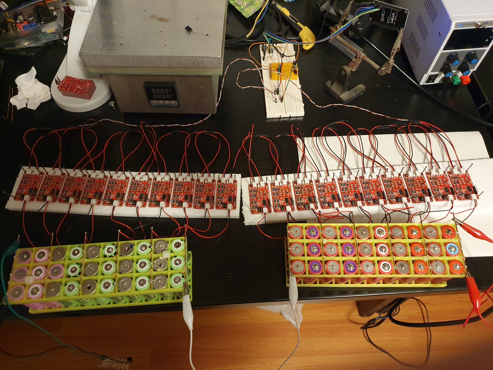
In other new’s I removed all but one BMS from the string of 7 and connected that the the older Wemon card I have. Both are running the Pre=complied code from before this version. Sorry I don’t know a version number.
As of now I’ve had no lockup. I’ll add another card every 24 hours until I start seeing issues. I’ll replace the potentially faulty card if I can identify a particular one.
I have tested to do the program with a nother programer for the moduls. The only change is thet the blue led blincks now to. But no change in voltage.
Every thing else works. It is so frustrating… i cant think of more to do.
I have duble cheked thet every component is the right one, and it semes to be so. I have resolder every thing. Checkt the code, nothing wrong ther. The voltage problem is in the modules i think. Becaus it reports high voltage from the first time i plug a modul in. It is the same problem whit every one of them.
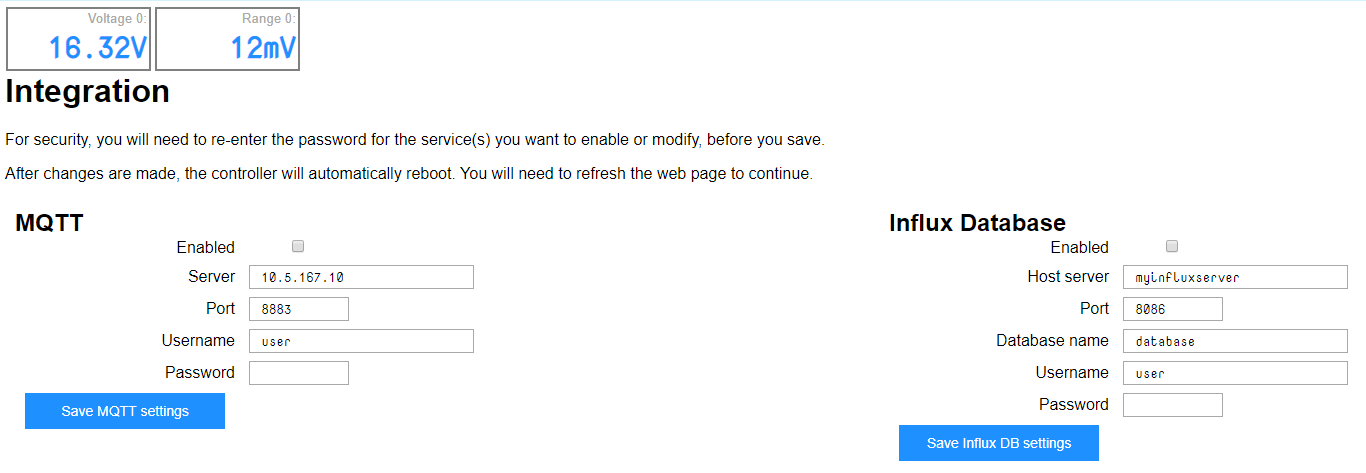
Until i changes the settings. But it do nothing more then bring the voltage down on the website. It never changes, only if i change it in the settings. But its never show the real time feed of the voltage reading.
Program this to one of the modules - it will run through a sequence of flashing the green/blue leds and every 10 seconds it will enable the dump load resistors for 2 seconds (don’t leave it running for ages as it will drain the battery).
It also permently enables the 2.408V reference so we can do diagnostics.
Using a multimeter - measure the voltages on the sensor1 pins:
Negative is at the bottom right of the board, nearest the power input connector.
TAKE CARE THERE ARE NO FUSES ON THE MODULES SO DON’T SHORT OUT THE PINS
Take a reading of pin 5 (negative) and pin 4 (positive) it should read the same voltage as your battery. Mine reads 3.605V
Take a reading of pin 5 (negative) and pin 2 (positive) it should read 2.048V
Using the pin5 on these sensor as the negative, probe pin TP2 near the ATTINY chip - it should read about 45% of the voltage of the battery. Mine reads 1.621V
ALSO ON THE ABOVE, DON’T TAKE THE READING WHEN THE RED LED IS ON!
MAKE SURE TO DISCONNECT THE ISP PROGRAMMER AS WELL
Latest pre-compiled firmware has been released, this includes 2 new features and 1 bug fix for the controller - the cell modules are not changed.
The 2 new features are:
Emergency Stop - you can connect an emergency stop button onto connector J1 (controller) when activated, this triggers the new emergency stop rules
Issue number #5 implemented - rules on low cell voltage
Bug Fix
WIFI configuration reset, on power up the green LED will light for 3 seconds - during this time you can activate the jumper pin to reset the wifi configuration in the ESP module
@stuart
Spot on!! How can i have missed thet. Thought i cheked every thing over and over. I can se on my order now thet it says 475 ohm and not 475k ohm . Cant say if it was me or the suplayer…
Thank you for all the help!!
Every thing works now!!! so so Grateful for your helpl!!
Hello
Interesting project, congrats.
Question: I guess it’s possible to use NIMH or even NiCd batteries if we monitor 2 or 3 cells in series.
What will be the minimum voltage we can monitor?
By the way, I have no intention to balance these cells.
Thanks
Not sure if this is the appropriate forum and whether this topic was covered somewhere else, but a quick search did not reveal any Eagle related posts…
I started the long journey of building a DIY/HBPowerwall a few months ago and was pondering the viability of spending $large on the Batrium Longmons, when stumbling across a forum discussing your diyBMS project - and was immediately intrigued.
I ordered the components from LCSC and the boards from JLPCB the very next morning, but missed some important parts - the ESP controller board, ATTINY841, IRLML6244, HMHA2801 &
NTC thermistors - due to over-eagerness & LCSC stock constraints…the latter being satisfied by RS Components at an elevated price.
The ESP controller board did cause some concern, since I would be paying shipping fees again for a single board - so I decided to try to produce my own backyard version. I’m not too familiar with KiCad and slightly more comfortable with Eagle CAD, and decided to try my hand at doing a single layer board of the ESP controller circuit.
I am quite willing to share the Eagle schematic, board & some photos, but am not allowed to upload any attachments at this stage…
You are now, I’ve elevated your status, as you’re clearly not a spammer.
(We prefer you upload to here rather than 3rd party sites. If those go down or the data is deleted for any reason, much if not all of the value of your contribution here will be lost.)
Hello, I have constructed setup to monitor 20s48p and now I am in phase of testing.
First I was testing 10S module for a week, and everything was good.
Now I have connected 20S, and… Sort of problems…
First - I needed to split to banks. Well, assigning to bank1 is not working flawlessly. You select battery, change bank, and - it does not change on next read. Than, you assign once more… Well, re-assigment took quite some time (15 minutes?).
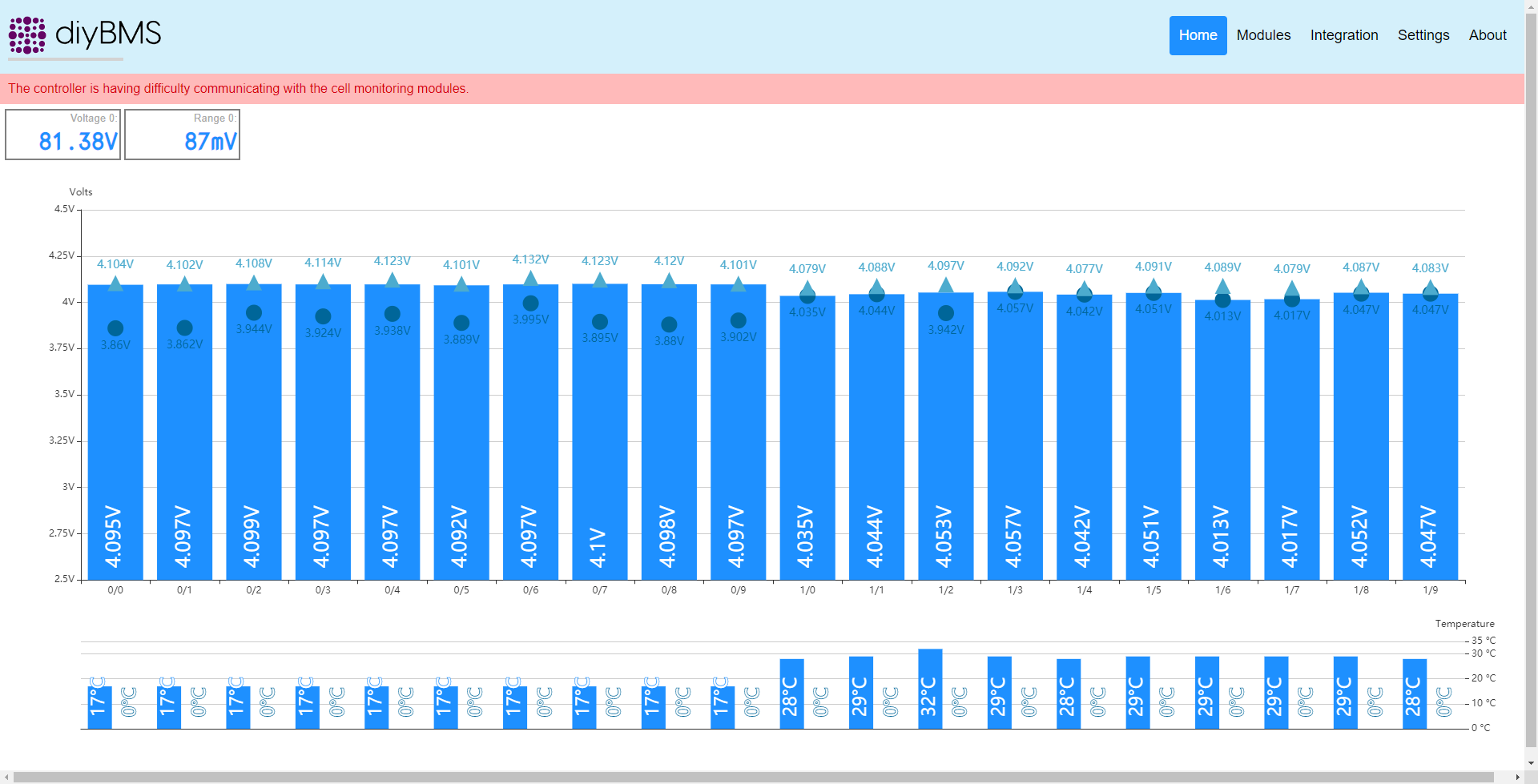
Now, when I have 2 banks with 10 modules in each, in “series” mode, reading values is - odd.
First - I do not understand error on top. There are no error packets but problem is shown.
Than, onboard thermisor is… well, yesterday when I have left all running, temperature was around 27-28C, and all boards were showing this. Now, real temp is around 17C (turned off heating), but bank1 shows wrong values?
Yesterday I had strange situation where measured voltage was like 2V (bar pointing down), and was not refreshing until I have reset esp8266 (I have nodemcu, not wemos).
Since this is still in test mode, is there something I can test/debug/help?
Or, someone can help with this “too big” setup for one bank?
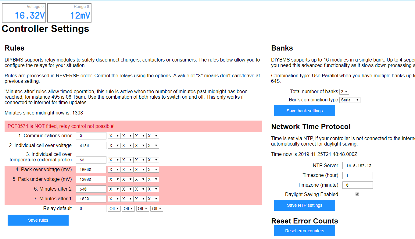
The bank configuration wasn’t heavily tested as most folks were using 10-14S setups, so this is a good test bed.
If you have 20S and “series” mode selected then you need to assign the first 16 modules to bank zero, and the remaining 4 to bank 1. This should get rid of the error message (because it cannot find module 0/10 right now).
Because you have the red error message, the bar graphs are not refreshing properly - the above should fix that and you will then see the correct voltages and temperatures.
The way you have it configured now assumes its a “parallel” mode - where you would have two 10S battery packs.
Hello,
Thank you for fast response.
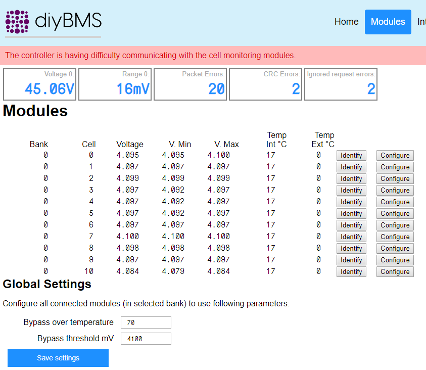
Well, I have tried to change from one bank to other, and… well, first, it is hard to get configuration open. You wait, wait, click, click… than you get:
Packet errors, CRCerrors, Ignored request errors
So, this is a bit hard to reproduce, but… if you have idea how to reproduce…
I will try to re-assign to 16+4 mode, but it will take some time.
It seams to me like it would be good that I do some testing of this, but you will have to lead me on this.
As this is “on trial” I am open for testing/helping.
Hi,
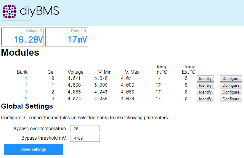
Just to inform. After 30 mins of trying to switch modules from (was wrong:bank 2 to bank 1) bank1 to bank0, I finally have finished moving, and after I have moved last one, I got:
I can confirm that I did not have any errors for 1 week, and none is messing over cables (no one is in that room).
I went there, reset nodemcu, lights start flashing all around and I get just 4 modules listed.
 . Cant say if it was me or the suplayer…