There is already TCA6408APWR chip using address 0x20. But you can do steps in this post DIYBMS v4 - #4319 by uqfus and you should be able run controller board with PCA9534.
hey everyone, could one of you kindly point me to this file
“*5 Click Browse and select the file “diybms_controller_firmware_espressif8266_esp8266_d1mini.bin””
as I cant seem to find it on stuarts github under “programming the controller”
thanks
PS not even github can find that file.
Click on Actions and select the latest ESP8266 version such as: Fix platform version for espressif8266 (#122) · stuartpittaway/diyBMSv4Code@87f6de1 · GitHub
nice, thanks
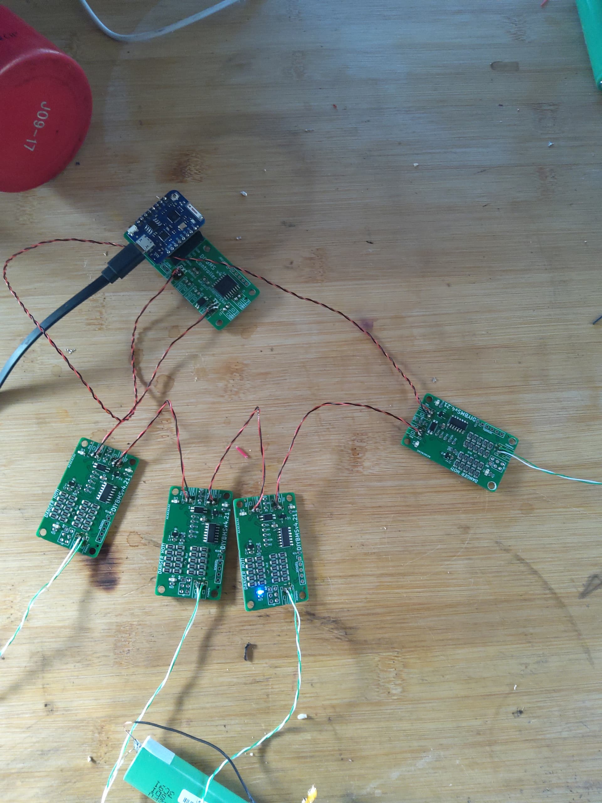
Could someone check my wiring? I cant seem to get the modules to respond.
Tx!
[Edited to show the image. Moderator (RW)] ← thanks Robert
AFAIK it’s wired correctly as in switched… But my modules won’t start in the correct order or sync
Umm, why are you connecting + to - ?? that cannot work. you need to connect pin1 of Tx to pin1 of Rx instead of swapping Pin1 with Pin2.
Funny you should ask, I had it 1 to 1 but when the didn’t work either,I went lookin for a wiring diagram and found some where there were switched here in this thread. Thanks for the clarification though. Doi
Maybe they weren’t responsive because the power was too low
Edit.
So I switched it back pin 1 to 1 and still no dice.
Hi
I’m a little confused and have 2 questions.
-
on all videos and pictures I can see that the esp32 controller is equipped with C8, C9, R22, R23, D6. The ATtiny841 is always missing. These are listed in the BOM file but are not used with jlcpcb. I assume this is related to the cpl file. Should I equip c8,c9,r22,r23,d6 or can I ignore them?
-
Do I need 32 balancer modules with an S16P2 battery pack?
You can ignore all the parts related to the ATTINY841 on the controller board. These have also been removed on future versions of the controller PCB.
For a 16S pack, you need 16 modules.
Ok, this is going to be more difficult for you because of the missing JST connectors.
- Start with a single module and get that working, then add on more as you go.
- Does the LED on each of the modules flash every 8 seconds?
- TX connects to RX, as @Smurfix mentions, pin 1 to pin 1 and 2 to 2.
- If you loop the TX and RX on the controller together (no modules), you should see the “ignored” message count increase on the web interface.
Note that the ESP8266 and the older style controller are no longer actively maintained or developed, all focus is on the newer ESP32 controller.
I checked my connectivity and seem to have a short in the com line somewhere, so yes, I’ll give it a rewire and try as you suggest. Thanks Stuart.
On the 4.0 controller board there aren’t any pin markings, so it’s also a bit of hit and miss, thankfully the module boards hat rx1 and tx1 marked.
Stuart, can I use this board without these chips? I ordered the new one a while back but haven’t gotten any of these missing chips yet for it.
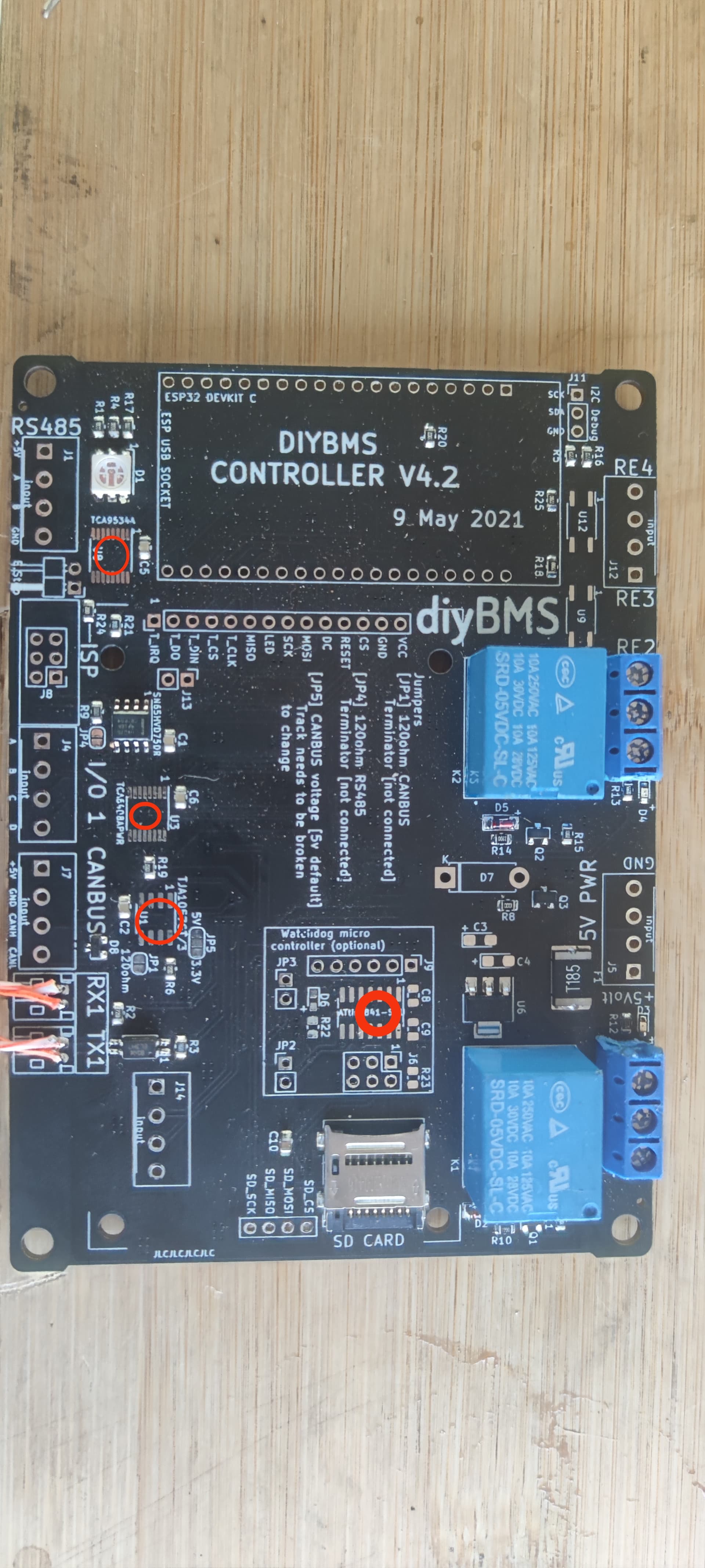
It won’t work without the chip in the top left.
Is CANBUS only compatible with Victron? I have a SMA Sunny Island and would like to build another DIYBMS pack for this inverter but really need CANBUS integration to control charging.
Here is the data that Sunny Island is expecting from diyBMS. If I compare this to victron_canbus.cpp code, it seems to hit all of the required data, so I’m optimistic it would work.
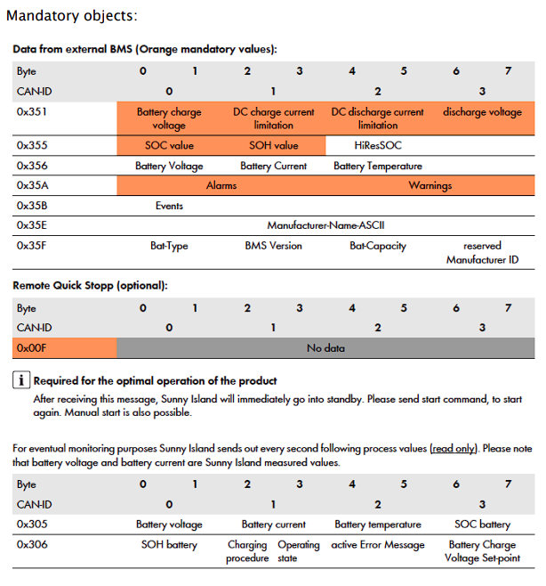
The code has not been tested against the sma devices, but if you can try it, that would be excellent.
I only have the earlier version of the board without Canbus pins. I’ll start a new build. I’ll check back in with you in about a month or two and let you know how it goes. haha! ![]()
10 posts were split to a new topic: NOV2021 branch (work in progress)
i will test this with my sma sunny island, if i can manage to program the shunt pcb…
Hi, thank you for the detailed explanation. Can you send me the compiled firmware with the modification you mentioned?