DIYBMS v4

that was what I meant, perhaps with little luck because of my limited knowledge of the English language. The fact that current is flowing through the wire modifies its resistivity and consequently affects the voltage reading of the next wire. Not due to the effect of heat that has an impact but very small. But because of the change in resistivity of a cable through which current is already flowing.

change resisitivity -it is small change, voltage drop on wire is your problem. With balance current 1A and 1m wire lenght 0.25mm2 (AWG 30) is over 68mV voltage drop… If you have only one wire to next cell detect voltage, this voltage drop increase measured voltage on next cell, and this (may be) balance on. This is start chain reaction when cells voltage tightly to balance voltage…
Maybe “big” resisitance on power wires on pack please isnpect this. Voltege drop between cels may be next problem.
resolution: increase wire thicknes, decrease wire lenght. Inspect power wires on pack.

Exactly, that is exactly what I was trying to say. Resistance/resistivity is a property of the metal, and changes by a minute amount with temperature - a fraction of one percent. I’m sorry, @Chapulino, you are wrong, the problem is without doubt the additional current as @kodl1 says. We call it the “I.R drop” from the formula for Ohm’s Law: V = I.R

The resistance change is very small, you can calculate it from:

R = R20(1+α20(T-20))

Where
R20 = the resistance at 20°C
α20 is the temperature coefficient of resistance at 20°C
T = the temperature (°C).
For copper, α20 = 40 × 10-4

thanks Robert for the clarification.

Ah interesting, I think I have also bought the same chips from the same seller. Are you able to share a picture of the modifications you made so that I can try and do the same?

Warning! This is for fake chip from china that i am received. Do not do it if you do not sure that it helps!
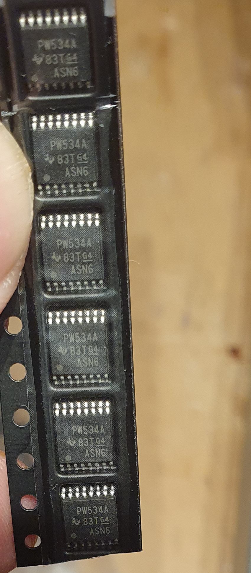
Chips i am received from china. Production code are same on all chips. But they default I2C address is 0x20


In file “\diyBMSv4ESP32\ESPController\include\HAL_ESP32.h” find TCA9534APWR_ADDRESS and replace with 0x23

//GPIO34 (input only pin)
#define TCA9534A_INTERRUPT_PIN GPIO_NUM_34
#define TCA9534APWR_ADDRESS 0x23 // 0x38
#define TCA9534APWR_INPUT 0x00

5 Likes

Hey @stuart
I have a 72V 200Ah Li ion battery pack do you think its advisable to try this as a BMS for that ?

It should work okay for that.

long post, but quick Q for @stuart or anyone that has gone through the code in detail.
built a couple of v4.4 modules and a ESP32 board (the modded one I’ve done with alternative DIP16 takeoffs for testing alternatives to the two TCAs and a DIP8 for the canbus chip.
Populated it with a PCF8574AN DIP16 instead of the TCA9534A. TCA6408 spot empty, no near equiv DIP found yet…
Initially wouldn’t pass the boot phase (unsurprisingly…) commented out two Halt lines in HAL_ESP32.cpp (l278 and l312) and now boots up with the D1 led showing red, screen on, but with two errors looping constantly on putty:

file: “src/HAL_ESP32.cpp” line 60
func: esp_err_t HAL_ESP32::writeByte(i2c_port_t, uint8_t, uint8_t, uint8_t)
expression: i2c_master_cmd_begin(i2c_num, cmd, pdMS_TO_TICKS(100))
ESP_ERROR_CHECK_WITHOUT_ABORT failed: esp_err_t 0xffffffff (ESP_FAIL) at 0x40091293
file: “src/HAL_ESP32.cpp” line 113
func: void HAL_ESP32::Led(uint8_t)
expression: writeByte(I2C_NUM_0, TCA9534APWR_ADDRESS, TCA9534APWR_OUTPUT, TCA9534APWR_Value)
ESP_ERROR_CHECK_WITHOUT_ABORT failed: esp_err_t 0xffffffff (ESP_FAIL) at 0x40091293

didn’t have enough time to get into the code much (only spent an hour or so, will do during the w/e). Remember I want to test canbus and venusOS - cells arrive end of Jan, so plenty of time to test with a raspberry running VenusOS at home.
I can edit wifi settings, then thing fires up, got it into programming mode, programmed the two successfully built modules (crapped out on the first one initially, then resolder the ATtiny, now is fine)
set a 4S config, wired the two up properly, hooked up a 18650, but nothing happens. As in no leds flashing on the modules, no voltage reported on the webinterface, screen stays on saying Stabilising.
So, after this intro the Q is:
is that normal behaviour due to not having the two TCAs in the controller board, or have I messed something up?
is the programming of the modules done right without the TCAs or it’s a bogus process as well? interface reported it’s done successfully.

If it’s OK, I’ll have a go at the code - any quick heads-up welcomed.

cheers

V.

1 Like

The TCA chips are largely there to control the relays and I/O - so basic comms with modules should work.

If you connect one of the modules to a cell, it should flash the LED every 8 seconds - this indicates the code is correctly programmed to the ATTINY.

The “Stabilizing…” message means the controller is waiting for a reply from all the modules connected to the system - it will stick on that until a reply is returned.

Try connecting the RX and TX connections on the controller together - it should then move on, but show lots of “ignored” errors in the web interface.

Double check the wiring of the JST cables between modules, make sure you have the correct pin mappings.

thanks @stuart

turns out that I made a kindergarden error and forgot to rebuilt the GND copper on the front of the module PCB :frowning:
took me half an hour to wire under a dozen GNDs to real GND on one module - will have to built another batch for sure, not fun doing that…
So now, with bat on, unconnected (or connected) to the controller, the green led sort of double flashes every 8 sec. Means code on ATtiny is fine.
However, no coms to the controller board according to the webserver, nothing on modules either.
I’ll check all the routing carefully, but with no one piece in established working state things are not that easy.

BTW, which of the three versions of V440 should I be using? tried all three, no difference!

cheers

V.

where do I find this file?

diybms_controller_firmware_espressif8266_esp8266_d1mini.bin

In the release section of here…

Found it here through a web search Releases · stuartpittaway/diyBMSv4Code · GitHub

Next question do I need to use the file image and if so how do I send to the D1?

forget the last question found it by reading over your instructions. Only problem now is the D1 cant be found by my router. It doesn’t look like its broadcasting. Only reason I reflashed was due to the controller not communicating with the module board, really don’t understand any of this any more its gone way beyond my limited technical skill.

OK have the D1 back online so I’m down to the controller and module board not communicating.
I have verified the cell module works V4.21 by using my existing working D1 and control board setup.

When I originally got the D1’s I went and downloaded the firmware but not the library files due to the controllers not being completed. This was about a year ago. The controller board is a V4 with a small 1. Seems i needed to upload something other then just the D1 firmware with the controller connected. Guessing this is why I have a communication issue.

So question is: is there any other file that gets uploaded to D1 or controller if your using the older style controller?

I’m trying to experiment with the high speed comms code.
The 4.4 modules and controller communicate fine at the default speed.
I’ve reprogrammed the modules with the 9k6 code.
When I try to choose the “Communication Speed” on the controller web interface the only choice I see is “Standard”.
I tried reprogramming the controller and starting from scratch but standard is still the only speed I see.
I’m sure I saw 5k and 9k6 earlier today?
I’m using the controller and module code: Compiled_Firmware_2021-11-09-17-42.zip
I’ve tried two controllers and different browsers on different hardware but still only one speed choice??
Doesn’t seem to make any difference whether modules are connected or not.

I still seem to have spontanious reboots when InfluxDB 2 integration is enabled. Less often than before, but still irregular. Sometimes within a day, but mostly after 3 of for days of uptime. Now that I turned it off I get a uptime of 5 days for the first time.
I was wondering if other people are experiencing this too?
I have not explored logging and visialization with MQQT and EMONCMS? yet, but I am allready wondering what uptimes people have when using the mqqt-integration turned on. I do not have a raspberry pi, but can run VM’s, although a PI VM is somewhat dated (and not 64bit).
Before I start reading and testing with mqqt and emoncms have any of you got some tips or pointers to set this up and achive vizialization like grafana dashboards?

I am using the firmware released on 5-oct-2021, with v4.21 modules.
@stuart do you prefer a ticket raised on github for this “issue”?

Thanks guys!

This is a bug in the web console. Please change the speed before flashing the modules :slight_smile:

Yes, use GITHUB please.

1 Like