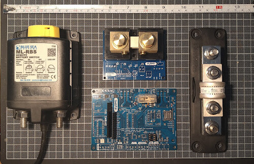
I’ve got all the kit I want to fit on my desk thinking how to wire the lot. Due to space constraints, I’d like to have them like in the following pic:
starting from the bottom right, + from bank going to the lower terminal of the class-T fuse
then passing to the left to the in of the shunt,
then over to the BlueSea 500A bistable relay
finally off from the far left port to the boat el.panel.
considering that I may be seeing 120-150A for half an hour occasionally (watermaker plus other bits running) do you recon it’s safe to have the BMS board in between there?
Plan is to get a piece of 20mm ply 350X250mm in size and securely bolt all that, get proper cables crimped and have the lot as one piece to mount above the bank in a locker onboard.
am I missing something?
EDIT: other than the 3A power supply for the BMS which is now in use on the testbed next to my desk!
Its really difficult to know if you are going to run into interference with the battery/inverter cables. I’d suggest that you will with 150A only a short distance away from the ESP32.
so I’ll get a slightly shorter piece of ply and fit the fuse, shunt and relay and keep the BMS board 150-200mm below next to the cells. Not as tidy as I’d like tbh, hope that RS485 comms from the shunt wont be compromised!
Alternatively I could use led sheeting to shield the BMS PCB but it gets complicated, ugly and of dubious results…
cheers
V.
PS. I see you’re busy pushing commits to the code, when should we expect a new code release to test? still get the odd reboot once every 4-5days…
I was thinking you could use a battery busbar or similar between the fuse and shunt and heatshrink that.
Might be a lot easier than cable and ring lugs. Similarly if you turn the relay the other way up you could twist a solid bar 90 degrees.
I was surprised to see this is what Tesla does with the connection between the charge port and battery, ie solid bar rather than cable.
I have the disconnect between the shunt and fuse/breaker so the shunt and BMS stay powered if there is downstream problem that causes disconnect.
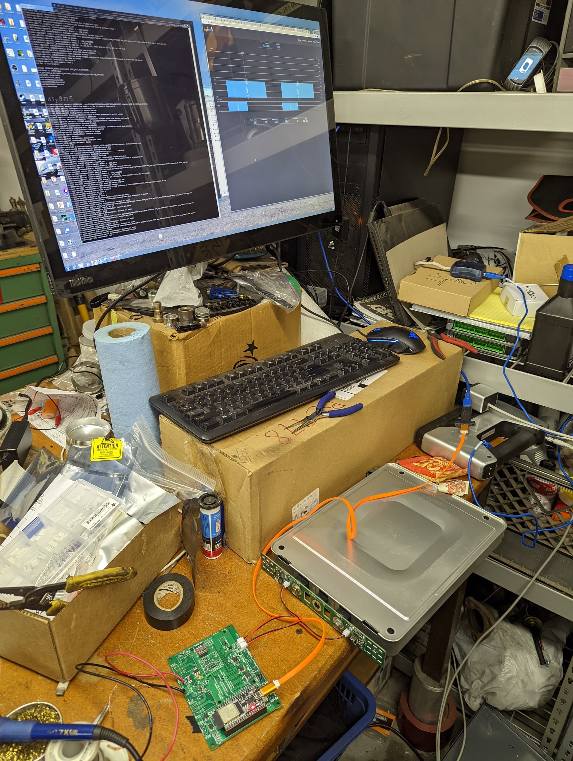
Figuring out what to do about missing components at JLCPCB
Hand soldering TSSOP 16 chips with a fat tip iron, lol
Dealing with 9354A vs 9354 i2c addressing (more tough soldering, lol)
Programming modules (I cannot for the life of me get the controller to program the modules, I had to use paltform.io, then had to figure out how to be use a avrisp mk2 rather than the asp as that’s all I have on hand)
Trial and error to figure out that the modules were reporting NaN voltage because I uploaded the wrong attiny FW. (The current leaf modules are v4.4 in case anyone else is looking)
But it works, very excited! Thanks for the help folks.
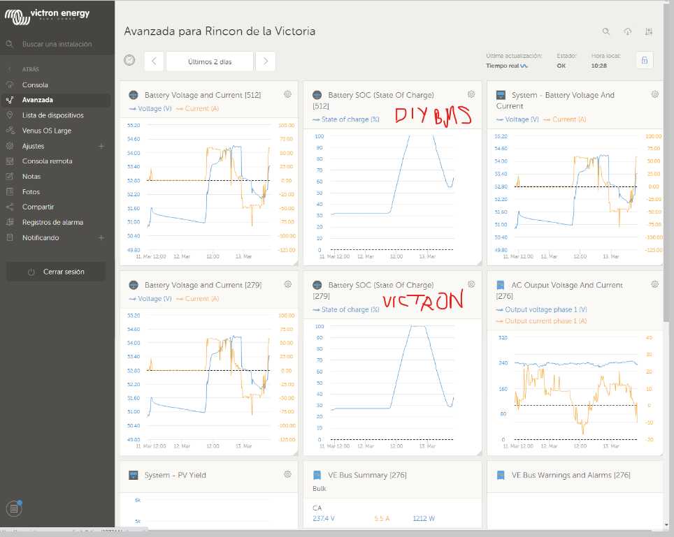
Could someone guide me to understand why this happens:
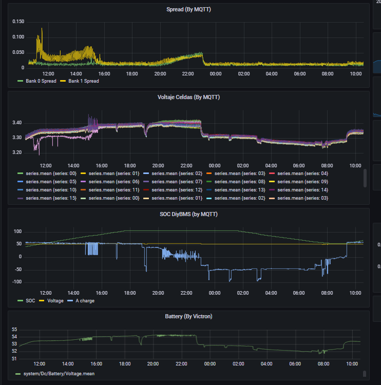
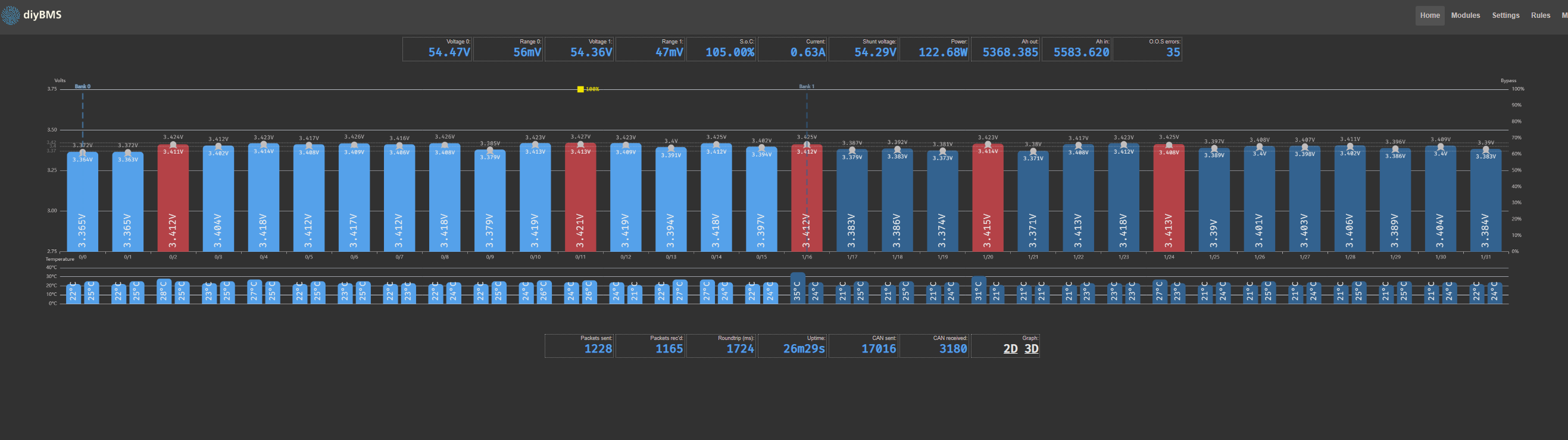
I have observed that after about two weeks, the DIYBMS SOC distances itself from that measured by the Victron BMV, approximately that of Victron after two weeks drops to 25% unlike that of DIYBMS that logically as it is the one that controls the installation does not drop below 30%
Another thing that happened yesterday is that I tried to charge the battery up to 100 . In the end I lost patience because the last section of charge controlled by DIYBMS takes forever with short charge cycles at low amps and stops when a cell starts to balance. The fact is that this was yesterday, but this morning I had the SOC of DIYBM at 60% and that of Victron (BMV) at 30% approx.
add some image
Theres a LOT of changes to the code, generally migrating away from Arduino style libraries to the native ESP32/IDF libs. @atanisoft is also helping a lot (thanks) this includes a re-write of the MQTT and Influx integration, so I’m hoping that helps with the random reboots.
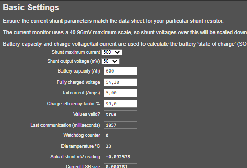
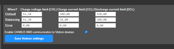
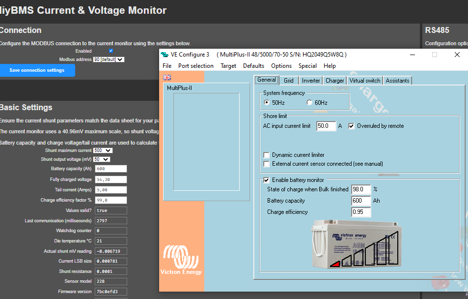
I think Victron’s is the correct one. but look, I have something more configured because DIYShunt is not set to 100%
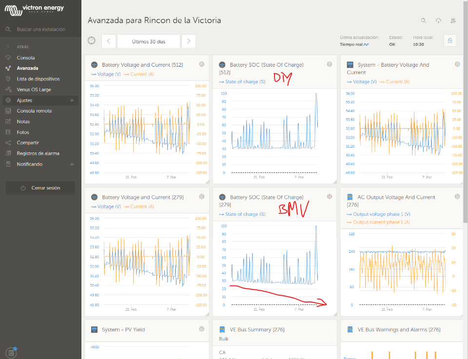
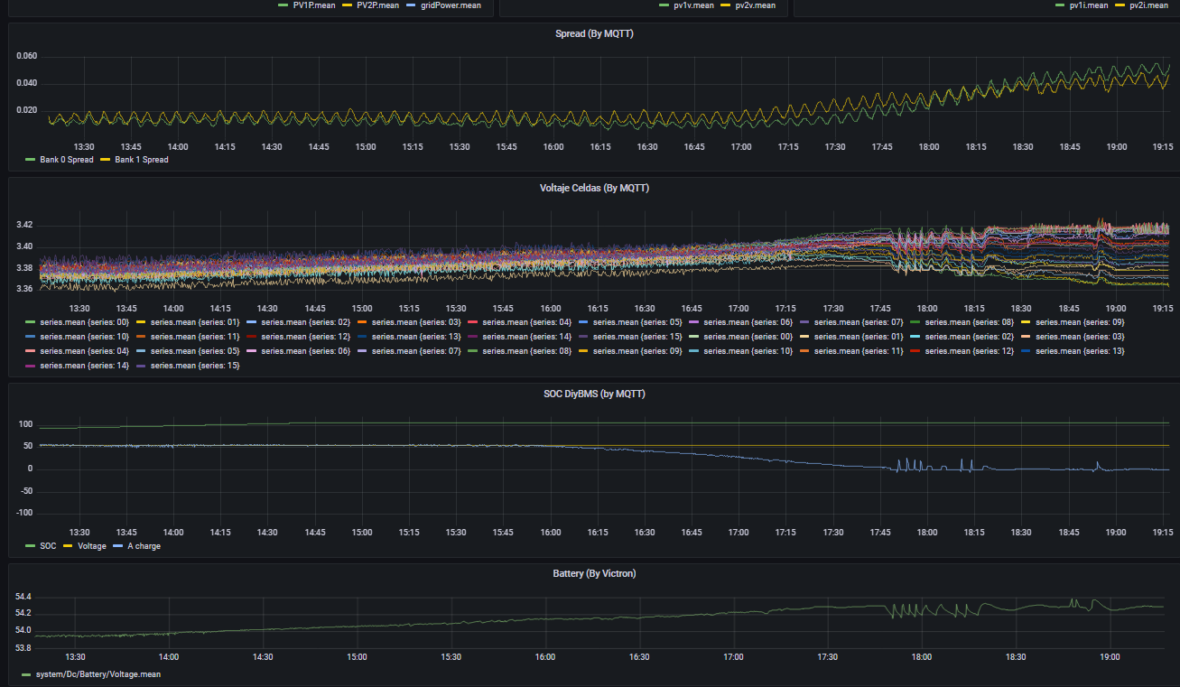
Look, at 02:00 p.m. the shunt began to rise from 100%, at 4:00 p.m. the load began to reduce, but from 5:45 p.m. it should have, because the load was lowered from 5A, I changed the SOC to 100%, I also left the configuration that I have in case I miss any detail.
Stuart I don’t know if it helps you, but this is the first 100% load I’ve tried since I updated the driver to the latest version.
I have a spare busbar from the 8 EVE cells, I could use that between fuse and shunt.
Rather, I’ll try and source a preferably plated copper bar. Wonder if I’ll find something locally.
This could be somewhat normal IF you are in the process of connecting modules one-by-one to the controller. If these persist though that is certainly not normal.
Hello Stuart,
I am making 3x12 cells pack, each of 12s bank will be connected via circuit breaker to common output of the pack. Is there a way to handle separately each bank by means of relay rules with one cntroller only and one relay board? I would like to disconect separately any of the banks when its cell/cells goes out of the limits.