@stuart
ive been meaning to ask you this… On about half of my cell modules they display a external temp without a thermistor connected to them… Any ideas?
Hi all. I can not understand why there is such an effect when balancing? I have 20S batteries and if one starts to balance, then two adjacent ones (left and right from it) also begin to do this. I measured it with a tester and indeed, the voltage on them increases. With what it can be connected?
at a certain point, you try even the weirdest thing to get the stuff running…
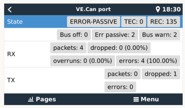
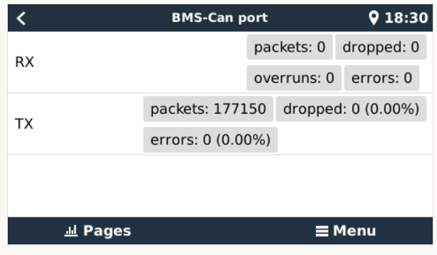
the diybms is connected to the BMS-Port and is terminated with a victron plug.
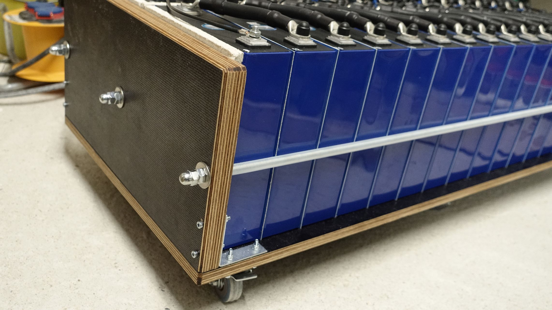
Very, very neat layout however i feel you have made a mistake on your approach to wiring up your pack.
In short it would appear you have one BMS and only 16 cell monitors. If so then you have to build a 2p16S battery bank.
What i see is 2 * 1p16s batteries attempted to be merged into 2p16s using very lightweight balance wires as commons between pairs of cells.
At best this is likely to give you erratic balancing and at worst be very unsafe in certain failure scenarios.
Moving forward you could either:
Option A:
Change to 16s2p and keep your existing heavy duty link cables, add additional BMS and additional 16 DIYbms modules
Option B:
Re-cable as 2P16S however very few of your beautifully made heavy duty cables will be of much use.
In general Option B is preferred by articles and videos i have watched.
I simply don’t have enough experience to say which is best - but to be fair one would have to understand the quality of cells, expected usage and charging to determine which would be best. Some argue option ‘A’ is slightly better if cells are of questionable matching quality as it allows you to easily identify cells needing extra attention / replacement.
i have made this for redundancy if one of the 16s pairs catch fire or a dead short happen, the balance wire will melt on the solderd spot and disconnect. i have tested this.
the “problem” is if one bank is not longer in operation because one cell died the other paralel cells will still equalize but the bms will stop discharging if this one disconnected battery will go lower than 2,5v
or if the other battery have a short that is connected directly to the bms the bms wire will again melt between these two cells and the bms disconnect because one cell is on 0v
in both cases i have to reconfigure the bms wires or exchange the damaged cells
there is almost no curent going through the wires in normal operation
but in general there are some “problems” in paralel configuration. it is not so easy to do with one bms, well time will tell
i dont want to use more modules because of the work, the costs and the lower system response time
i had to program 5k speed 9k had communication problems
Yes, i have.
Sadly i have no working system where i could swap compontents for testing.
Luckely i was able to order 5 completely soldered boards of the latest HW version from JLCPCB. They should arrive next week.