DIYBMS v4

@stuart i have the old controller with v4 modules running with the relays on a Victron system.

With the new controller using CANBUS together with Victron do i need the new shunt and/or can i still use the Victron Shunt i have ? Do i need new modules or can i still use my v4 modules to work with the new controller ?

All modules work with the new controller, although v4.4 if preferred if you have a large installation (50+ modules).

The BMS wonā€™t be able to read the values from the Victron current shunt, so it wonā€™t calculate the state of charge unless you have the DIYBMS current monitor device.

Both the current monitor and new style controller are difficult to build at the moment due to part shortages, although it does look like this situation is improving.

@stuart Ok but i would not lose anything than the diyBMS canā€™t read the SOC but rest would work ok i mean the DVCC, errors, status of battery. ?

I just tried today on JLCPCB and there were very few components that were missing so yes it looks good, i only tried the controller and the modules, not the shunt yet unless i will miss something without it.

btw. i only have 16 cells so it seems i can work with the v4 modules i already have

Yes DVCC would be okay, as thats just using some basic rules, you would also get the alerts from diybms into the Victron kit.

Most of the parts at JLCPCB are in stock for the controller, you can swap C3 and C4 for part number C110786 (part TC212A226K006Y), thatā€™s currently in stock.

The TCA9534A is still out of stock though.

ok so i am stiil not sure what am i missing if i donā€™t have the current monitor and i use the victron shunt ? Any input would be great to know if itā€™s worth doing that one as well or i can get away using the victron for now.

I can see that TCA9534A is available with Mouser https://www.mouser.dk/ProductDetail/Texas-Instruments/TCA9534ADWR?qs=0C8XhJW8e4rLc8P%2BNxTT0A%3D%3D looks correct yes ?

1 Like
ets Jun  8 2016 00:22:57

rst:0x1 (POWERON_RESET),boot:0x13 (SPI_FAST_FLASH_BOOT)
flash read err, 1000
ets_main.c 371
ets Jun  8 2016 00:22:57

rst:0x10 (RTCWDT_RTC_RESET),boot:0x13 (SPI_FAST_FLASH_BOOT)
configsip: 0, SPIWP:0xee
clk_drv:0x00,q_drv:0x00,d_drv:0x00,cs0_drv:0x00,hd_drv:0x00,wp_drv:0x00
mode:DIO, clock div:2
load:0x3fff0018,len:4
load:0x3fff001c,len:1044
load:0x40078000,len:10124
load:0x40080400,len:5828
entry 0x400806a8


                _          __
    _|  o      |_)  |\/|  (_
   (_|  |  \/  |_)  |  |  __)
           /
[I][main.cpp:3285] setup(): CONTROLLER - ver:8b166ac4e93aa867cb3a07395ecddf2f87406948 compiled 2022-01-05T10:37:06.597Z
[I][main.cpp:3290] setup(): ESP32 Chip model = 1, Rev 1, Cores=2, Features=50
[I][HAL_ESP32.cpp:232] ConfigureI2C(): Configure I2C
[I][HAL_ESP32.cpp:291] ConfigureI2C(): Found TCA9534A
ESP_ERROR_CHECK_WITHOUT_ABORT failed: esp_err_t 0xffffffff (ESP_FAIL) at 0x40091293
file: "src/HAL_ESP32.cpp" line 60
func: esp_err_t HAL_ESP32::writeByte(i2c_port_t, uint8_t, uint8_t, uint8_t)
expression: i2c_master_cmd_begin(i2c_num, cmd, pdMS_TO_TICKS(100))
[E][HAL_ESP32.cpp:311] ConfigureI2C(): TCA6408 Error
[E][HAL_ESP32.h:181] Halt(): SYSTEM HALTED

Any idea what wrong with my controller, please help

TCA6408 Error

Either faulty chip, bad solder or a different chip varient to the one on the bill of materials.

Please forgive me if this is obvious, but I canā€™t find a summary of what the BMS does i.e. feature list i.e. balancing/overcharge/discharge etc. functionality. Am I missing something? Also, it looks like one would need one BMS per cell, so in other words, if I have a 4s4p configuration, I would need 16 boards?

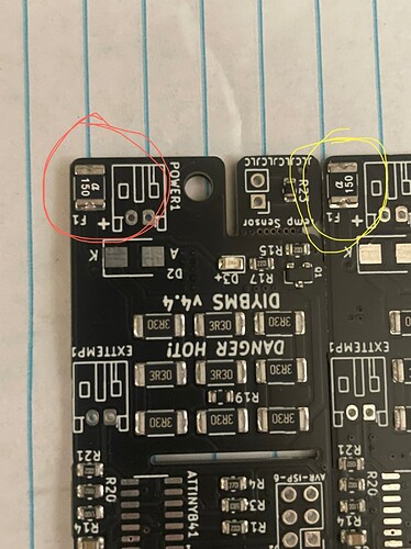
Does it matter these 2 are opposite orientation

Hij David, these are fuses the orientation makes no difference to the functionality. When you are going to place D2 you have to make sure the orientation is right.

How does D2 orientated?

D2 being a diode will have a stripe indicating the cathode side which should be soldered towards the K on the PCB. Did you recently order these and was the diode not available to be automatically placed?

Hi Dave, I donā€™t think Iā€™ve kept a features list updated for a while so here goes:

  1. You need 1 cell module per ā€œSā€ configuration - so in your case 4 modules
  2. You need 1 controller for up to 128 modules
  3. MQTT is supported (for external logging/monitoring)
  4. INFLUXDB is supported (for external logging/monitoring)
  5. Rules can be added to drive 4 on-board relays to trigger charging/fuses/breakers, for example, over temperature, under temp
  6. You can add on the current monitor shunt/board to provide accurate current and voltage measurement
  7. Victron CANBUS is supported to upload information into Victron and drive the DVCC functionality (still in experimental stages)
  8. Onboard logging to SD Card
  9. TFT display to show whats going on
  10. Wifi + Web interface for configuration

Think thats about it!

Having some issues with my newly built v4.2 control board.

When I run board test I get this output:

rst:0x1 (POWERON_RESET),boot:0x13 (SPI_FAST_FLASH_BOOT)
configsip: 0, SPIWP:0xee
clk_drv:0x00,q_drv:0x00,d_drv:0x00,cs0_drv:0x00,hd_drv:0x00,wp_drv:0x00
mode:DOUT, clock div:2
load:0x3fff0018,len:4
load:0x3fff001c,len:1044
load:0x40078000,len:10124
load:0x40080400,len:5828
entry 0x400806a8
ā–’[I][main.cpp:183] ConfigureI2C(): Configure I2C
ESP_ERROR_CHECK_WITHOUT_ABORT failed: esp_err_t 0xffffffff (ESP_FAIL) at 0x40090f67
file: "src\main.cpp" line 137
func: esp_err_t writeByte(i2c_port_t, uint8_t, uint8_t, uint8_t)
expression: i2c_master_cmd_begin(i2c_num, cmd, pdMS_TO_TICKS(100))
[E][main.cpp:207] ConfigureI2C(): TCA9534APWR Error
ESP_ERROR_CHECK_WITHOUT_ABORT failed: esp_err_t 0xffffffff (ESP_FAIL) at 0x40090f67
file: "src\main.cpp" line 137
func: esp_err_t writeByte(i2c_port_t, uint8_t, uint8_t, uint8_t)
expression: i2c_master_cmd_begin(i2c_num, cmd, pdMS_TO_TICKS(100))
ESP_ERROR_CHECK_WITHOUT_ABORT failed: esp_err_t 0xffffffff (ESP_FAIL) at 0x40090f67
file: "src\main.cpp" line 263
func: void Led(uint8_t)
expression: writeByte(I2C_NUM_0, TCA9534APWR_ADDRESS, TCA9534APWR_OUTPUT, TCA9534APWR_Value)

JLCPCB was out of TCA9534APWR, so I ordered them from mouser and hand soldered it on. My hand solder isnā€™t perfect, but I checked with a meter and I have no bridges and the LED lights up when the right pins are driven.

If I reorder the code to check the TCA6408 first, that chip seems fineā€¦

rst:0x1 (POWERON_RESET),boot:0x13 (SPI_FAST_FLASH_BOOT)
configsip: 0, SPIWP:0xee
clk_drv:0x00,q_drv:0x00,d_drv:0x00,cs0_drv:0x00,hd_drv:0x00,wp_drv:0x00
mode:DOUT, clock div:2
load:0x3fff0018,len:4
load:0x3fff001c,len:1044
load:0x40078000,len:10124
load:0x40080400,len:5828
entry 0x400806a8
ā–’[I][main.cpp:183] ConfigureI2C(): Configure I2C
[I][main.cpp:230] ConfigureI2C(): Found TCA6408
ESP_ERROR_CHECK_WITHOUT_ABORT failed: esp_err_t 0xffffffff (ESP_FAIL) at 0x40090f67
file: "src\main.cpp" line 137
func: esp_err_t writeByte(i2c_port_t, uint8_t, uint8_t, uint8_t)
expression: i2c_master_cmd_begin(i2c_num, cmd, pdMS_TO_TICKS(100))
[E][main.cpp:238] ConfigureI2C(): TCA9534APWR Error
ESP_ERROR_CHECK_WITHOUT_ABORT failed: esp_err_t 0xffffffff (ESP_FAIL) at 0x40090f67
file: "src\main.cpp" line 137
func: esp_err_t writeByte(i2c_port_t, uint8_t, uint8_t, uint8_t)
expression: i2c_master_cmd_begin(i2c_num, cmd, pdMS_TO_TICKS(100))
ESP_ERROR_CHECK_WITHOUT_ABORT failed: esp_err_t 0xffffffff (ESP_FAIL) at 0x40090f67
file: "src\main.cpp" line 264
func: void Led(uint8_t)
expression: writeByte(I2C_NUM_0, TCA9534APWR_ADDRESS, TCA9534APWR_OUTPUT, TCA9534APWR_Value)
ESP_ERROR_CHECK_WITHOUT_ABORT failed: esp_err_t 0xffffffff (ESP_FAIL) at 0x40090f67
file: "src\main.cpp" line 137
func: esp_err_t writeByte(i2c_port_t, uint8_t, uint8_t, uint8_t)
expression: i2c_master_cmd_begin(i2c_num, cmd, pdMS_TO_TICKS(100))
ESP_ERROR_CHECK_WITHOUT_ABORT failed: esp_err_t 0xffffffff (ESP_FAIL) at 0x40090f67
file: "src\main.cpp" line 264
func: void Led(uint8_t)
expression: writeByte(I2C_NUM_0, TCA9534APWR_ADDRESS, TCA9534APWR_OUTPUT, TCA9534APWR_Value)

Clearly something is wrong with the TCA9534APWR, but Iā€™m mostly procrastinating on removing/replacing it :frowning:

Hi @Geoff_B, looks like you are nearly there. As you have determined the code cannot communicate with the 9534 chip. Did you get the EXACT same version/model as the JLC/LCSC one?

Its possible different variants have different i2c address values, but I donā€™t know for sure. I suspect its a simple soldering issue, perhaps go over each pin with the iron a couple of times to check - particularly around the SDA/SCL lines.

To confirm this Iā€™d suggest using the arduino wire scan sketch: arduino-esp32/libraries/Wire/examples/WireScan/WireScan.ino at master Ā· espressif/arduino-esp32 Ā· GitHub

Just be sure to update the Wire.begin() line to read Wire.begin(27, 26, 400000) which matches the settings that diyBMS uses.

Ideally you should see address 0x20 (6408) and 0x38 (9534) respond. If you see any other addresses respond you may have an incorrect chip OR the address pin is no connected to 3v3 or GND as expected (if it is soldered to the PCB and the chip is correct it should work).

Also double check the orientation of the chip! Pin 1 should be oriented to the top left, towards the ESP32.

:frowning: as it turns out, no I did notā€¦

TCA9534PWR and TCA9534APWR differ only in the default slave addresses.

TCA9534PWR has a default address of 0x20 when all the address pins are low, which conflicts with the 6408ā€¦

I updated the board_test to give the 9534 0x20 and 6408 a bad address and now I get blinking red and green as expected. For funsies I set them both to 0x20 and the LED doesnā€™t turn on (poor confused chips).

Guess Iā€™ll try to re-address one of them, yay tiny tiny solderingā€¦

Thanks! This is exactly what I wanted to help debug and I was in the process of setting it up when I decided to double check the part number and found the above issue.

Seems, Iā€™m not yet allowed to upload things, but I have a blinking green light :slight_smile:

Lifted A0 on the 9534 chip and used a bit of wire to bridge it to VCC, setting the address to 0x21.
Updated the address in the board_test and weā€™re off to the races. Now to figure out how to program the ATTINY on my module boards (suspect it wasnā€™t working before at least in part due to the bad addressing)

Try now - Iā€™ve upgraded you.

Great, glad itā€™s working @Geoff_B