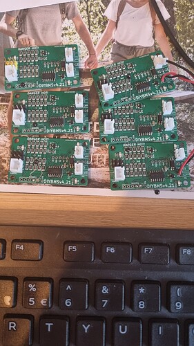
I have TX connectors red, on board and cable. Next level Is on my cell boards 4r7 resistors in series with input and optocoupler. If Is conection bad, smoking only 4r7 resistors…
I also did that, burn controller and screen and module all at the same time. I felt sick at that moment, anyways controller flashing red and green what does that meant
I suppose that’s true, but I don’t know how I would troubleshoot module communication errors without them powered.
The issue was that I was troubleshooting the install, after testing it with everything loose. Testing was correct, so I attached the modules within the cabinet, hooked up the rx/tx, hooked up the power cable, put the plexiglass over the battery with the 2 loose rx/tx wires out to the control panel. Plugged them (correctly) in with the power off, turned on the power to the control board, booted DiyBMS, and saw a communication error with the modules. Dang.
So power down the control board, unplug the rx/tx cables to get access to the batteries, double check the cable connections, try to position the controller so I can see the LEDs on the modules in the battery area, and plug in what I thought was tx. poof
ESP32 power LED comes on, but is immediately warm to the touch.
TFT screen didn’t turn on in my backup board with a new ESP32 after flashing. Not sure how else I could test this.
SD card isn’t readable in an adapter.
Next step is to sharpie the JST connectors for tx red, and pick up a new screen and SD card…
crap never thought it was possible
have just pluged in the cabels carelessly
is this only with 4.4 ? i have 4.21 modules running on new controller
now i will mark them
thanks
this will be the ultimate chipageddon, fry the controller with no chips availabile
Don’t do this!! I doubt you would do this with the main power cables coming out of a large battery pack!!
The same applies to the cables in the modules. Its definitely a design issue with the way the connectors are used, but I can’t start changing the connectors now as I would lose backwards compatibility.
Just be careful everyone!
If you’ve not seen the latest diybms video, take a look, explains what I’ve been working on and also the problems we are all facing in trying to build these devices.
There’s also a small controller code update to improve a few things.
development with LTC6803 is very exciting, cheer up Stuart. Although I’m so happy with the current solution that I don’t think I’ll change it, but I’ll sure have fun prototyping when you release it.
Controller LED flash red than green, no wifi from esp32 and use terminal connect to esp32 but it only show unrecognizable text. Any one know what going on with my controller
Means no communications with the TCA6408 chip.
The serial debug output should have these comms settings 115200 baud, 8 data bits, No parity. 1 stop bit.
Easiest way to avoid wrong communication cable connections is to place glue on TX connector with cable attached or solder one end of cable directly to module TX.
I have managed to “overvoltage” 6 of my modules, now they are unable to programm…do you think that just replacing the chip could be the solution? Or are more component likely to have been damaged?
Might be worth trying to swap out the ATTINY, most of the other parts should be better at handling higher voltages.
What sort of voltage are we talking about?
16-18v instead of the expected 4.1v im gonna try to order 6 attiny’s, thanks!
The mystery of the modules that do not communicate to 9k6
I have a group of 16 modules that work correctly in the standard speed but it is impossible for the controller to communicate with them at 9k6.
I have tried several things in some of them, changing the 8kHz resonator, changing the Attiny and in neither of the two cases have I been able to communicate them.
As a curious thing, if I only feed them without connecting RX and TX I have a sequence of an initial fast double blue flash and a fast blue double blink every 8 seconds.
I don’t know what else to do except resign myself to the fact that they can only work at standard speed.
The truth is that they are surplus because I have what I need for my installation and another 16 in reserve that do communicate to 9k6. I was thinking of giving them to a friend but I would like to make sure that if necessary they will be able to use them at 9k6
I don’t really know what to recommend in that situation.
If you have some modules that do work, and other that don’t, it would indicate a hardware issue somewhere…
The truth is that it is very strange because the elements involved in the communication are the Attiny and the resonator. I think that nothing more, the Attiny can be programmed without problems and I have tried to change resonators in some of these modules. This weekend I will remove attinys in other modules and put new resonators. The strangest thing is that the module stops blinking when RX and TX are connected. On the other hand, other modules with the same controller do operate at 9k6
LTC6803 sounds very interesting.
Any reason you stayed away from LTC6811 ?
None at all, there are a lot of devices in the LTC68XX range, some were released after I got samples of the LTC6803-3
![Chipageddon [diybms]](https://img.youtube.com/vi/u0oDGLGE5uk/maxresdefault.jpg)
