@stuart
It sames, thet ther is an error. How do i fix it?
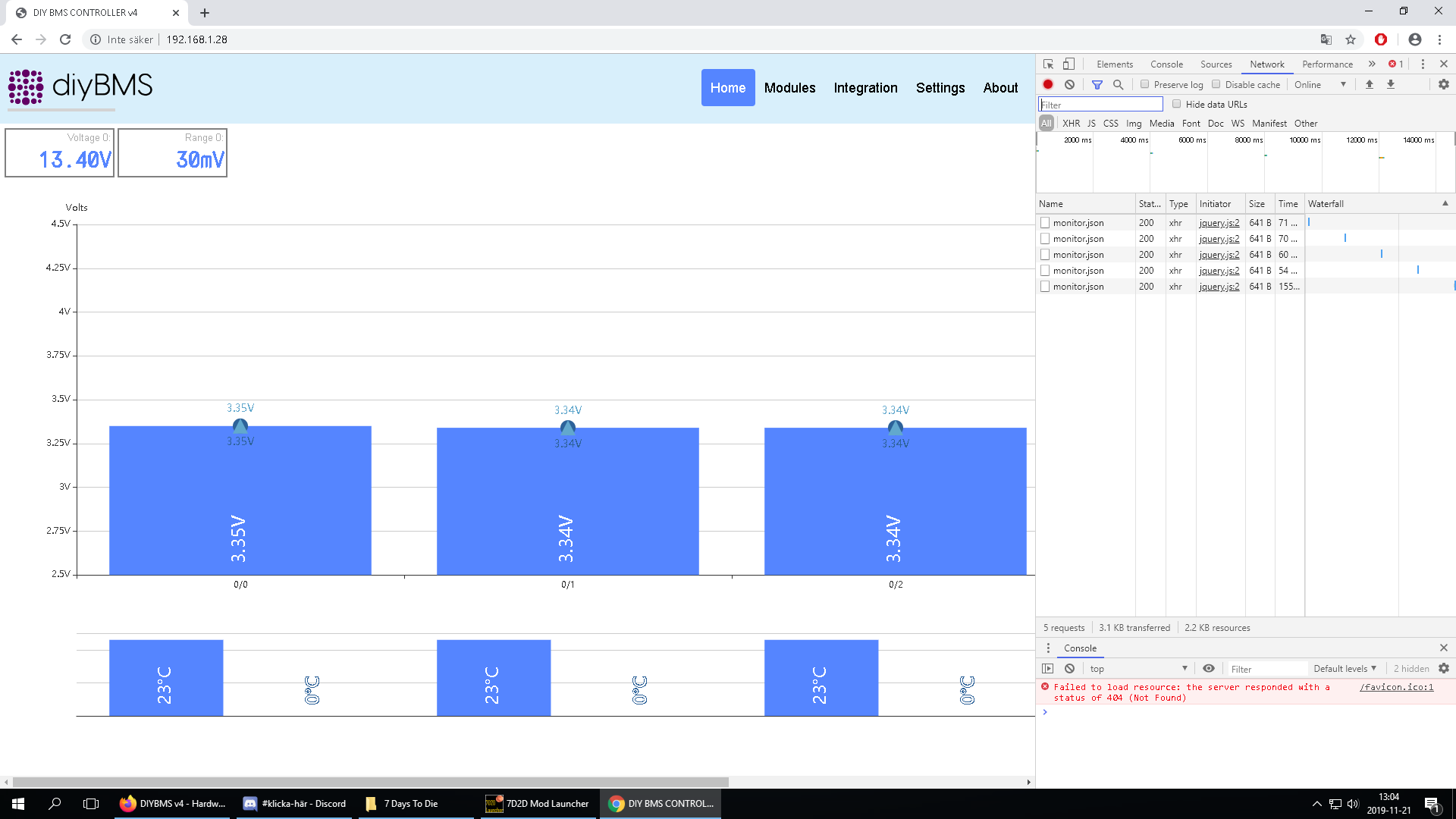
I have the wemos d1 mini pro if thet can be the problem. If i test to put the finger on the temp ic on the board, it reports the changed temp. So on some plane it sends data.
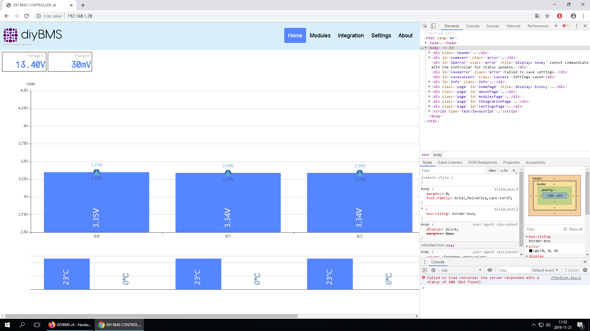
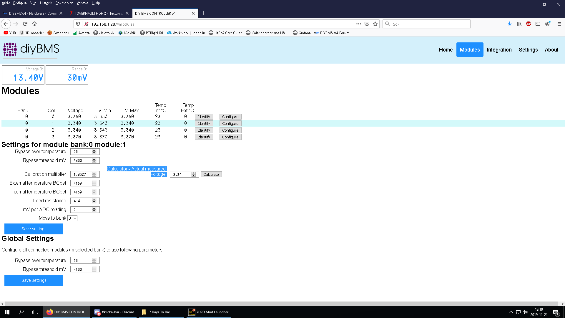
The first time i pluged every thing in. The module get directly in to balancing the cell. Every modul did thet. When i got the web page up and running i could see in the moduls tab thet every modul reported 4.75v, i think it is the max it can show. so i went in to the modul setting and changed the voltage under “mesured voltage” and then it stoped be in balancing mode. But the voltage wont flux and change. If i put a battery thet is fully charge it will still say 3.34 volt and thets what i put in.
thanks for sharing the V4! I’ve built 14 Cell Modules and everything works like a charm!
But I have some questions and suggestions:
In the V3 there was a setting to set the max/min voltage, shown in the bar-graph, or? Is it possible to include this setting? If not, in which file can i edit the code, to set the voltage range to (i.e.) 2.75V to 4.25V?
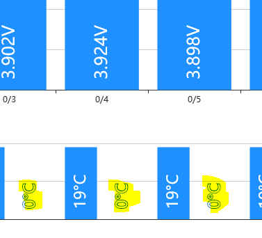
I don’t understand the temperature-bar-graph. Next to every cell temperature, there is a second temperature (0°C in my case…). Can you explaine this temperature please?
Is it possible to change the SSID/password in the frontend, so I can change the WLAN-setting, without flashing the Wemos D1 mini every time?
And a litte bit more off topic: I will use the BMS in my off-grid solar 2x 7s60p 8.6kWh 18650 lithium project. I have no router/access point for WLAN yet… What do you think, is the best/cheapest/energy-consumption-less 24V-solution to connect the D1 mini to an old Samsung Tablet, to check the voltages (once a week)? I thougt about a Raspberry Zero W (as access point) or, a mobile 3G/LTE WiFi Hotspot (Huawai). Is there a easier way?
Thanks!
Yes, It is Lifepo4 cells. But i tried 18650 lithium cells and it is the same. so i dont know, but i don’t think it is the cell typ thet is the problem?
Thets exactly what i have done all ready. The voltage won’t follow or change when the battery voltage in the real life go up or down… the value on the web page never change after the real voltage. I can sett it just like you described. But that’s it
yes, unfortunately I am still having lockup issues.
I’m going to start removing BMS’s from the loop one at a time and see how it goes. Maybe one is faulty. I’ll replace the linking cables as well.
I’ve moved from a testing phase (1 cell per BMS) to the full pack 7s22P) and it’s still the same. As previously stated I’m using the pre-complied code. I’ll make an effort to do it the proper way. Oh, and change the controller code as you mentioned above.
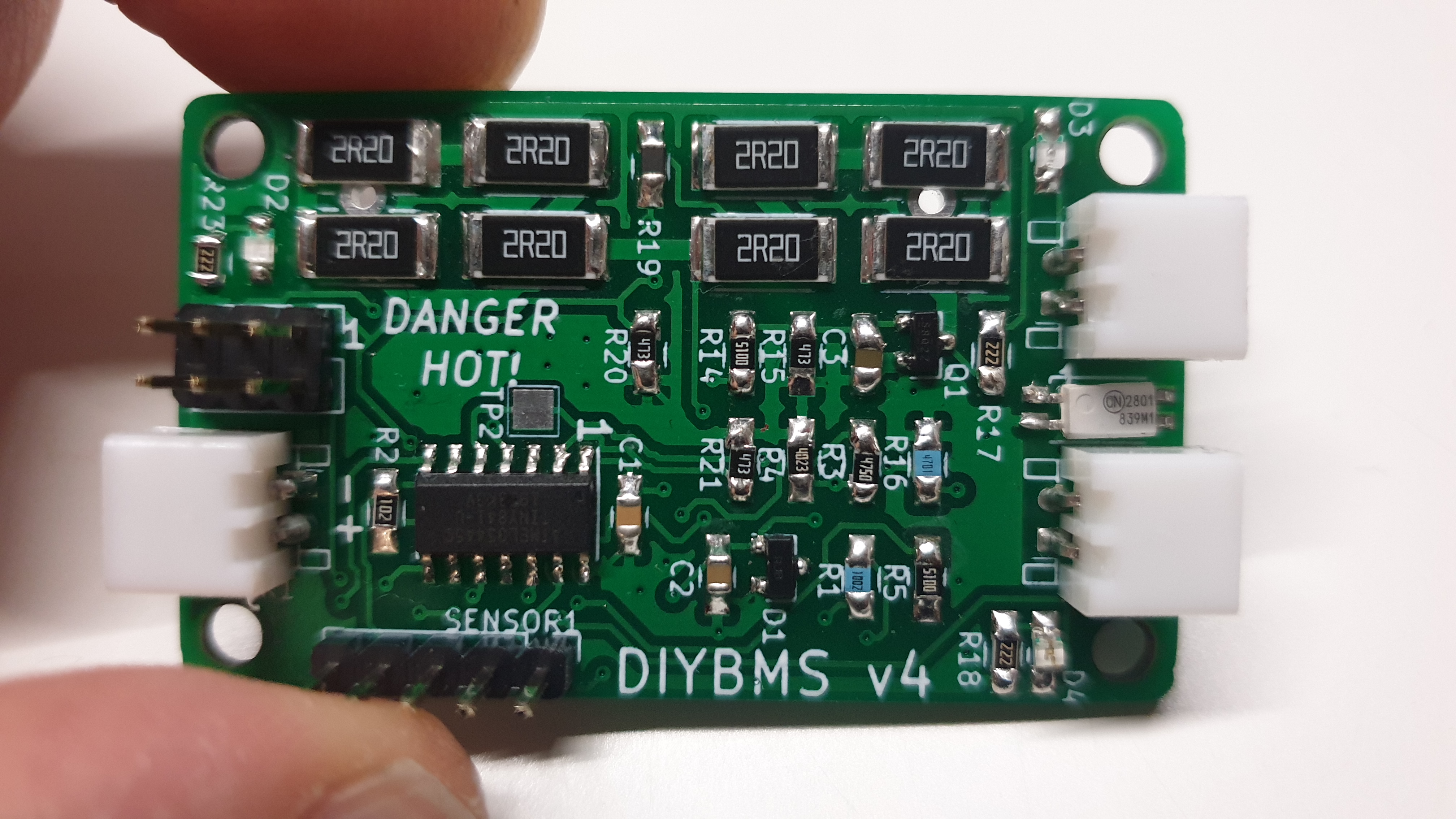
Ok if the voltage never changes all I can think is that the 2.048V regulator isn’t working properly. Can you check the soldering around the lm4040 chip?
How have you connected the modules to the battery cells?
The problem is white every modul i have tested x10. But when i test i get 0.55v betvin leg 13 and ground of the attiny841, every time the green led flashes. I have a 4 cell battery that is series connected. every module have a individual plus and minus till every cell
I am really grateful for all the brainpower you putting in to help!
I have turn the bord and komponents inside out and tried many different thing the past months. So i iam grate ful if you have the eys to look at the bord i have soldered, because i cant see eny ting wrong.