@stuart Is it possibile to develop a single board version (7s for example)?
@Edoardo_Conti sorry, no plans to do that - you can obviously use 7 of the modules to build the solution but I suspect you are after a smaller PCB size?
That’s right.
I’m working on a powerwall with Jehu’s DIY PCB design, you know?
It would be interesting to develop a version that fit with that design.
@Edoardo_Conti the existing design would work, just put a module near each of the PCB modules.
Looks like that each module is a 7S not a 7P so its harder to connect the dIyBMS.
I think that in this case it would be chaper for him to use an off the shelf 7S controller, and then attach a uC to manage the bypasses with a mosfet on each cell. Or he could use a cheper Inductive Balance Board to keep them always balanced.
I have never done experiments with the compartor ADC of an ATMEGA. But in such case you have 8 ADC pins and I’m not sure if there is a chip that have that much differential inputs!
The problem with creating a single Board S7 is that I’m going to then want a single board S14. Someone will want an S3 and so on.
Once you designed a modular board it shouldn’t be hard to expand the PCB for multiple configuration (3S, 7 , 8S [LiFePo4] etc…) . Am I wrong?
DIYBMS is already a modular board - it can go up to 64S (4 banks of 16 cells)
1 Like
Voltage seperation is the issue, you don’t want 48V going into an Arduino!
4 banks of 16 cells? does that mean 1 controller for 16 modules max?
Have you tested how worse it is?
The C variat is available from LCSC, so the guys can make a single order for both the PCB and the components!
No, 1 controller for 4x16 modules maximum (64 modules in total)
It will be fine - they do A/B/C/D variants all of different calibration/accuracy. “C” is still 0.5% accuracy.
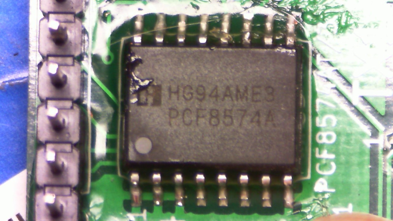
Hi. Any thoughts on this? 2 controllers I’ve made report “PCF8574 is NOT fitted” on the Setting page. Checked soldering etc.
Pic for you to tell me I’ve ordered the wrong version.
Any thoughts on the lock up Issue? I’m close to completion of the battery
Thanks
Hi every one!! I want to start to thank you Stuart for a great work!
I Have a problem. The voltage wont change when i discharge the battery. I can set a fixed value but it will just stay ther. Temp works and every thing else. It is the version 4 of the board.
what can be wrong?
Thanks for replies!
Welcome.
I assume you have it all working, wired and the controller working and showing a web page?
Any errors on that page? What exactly is the issue? The cell voltages are not dropping when under discharge? Not balancing right?
Thanck you!
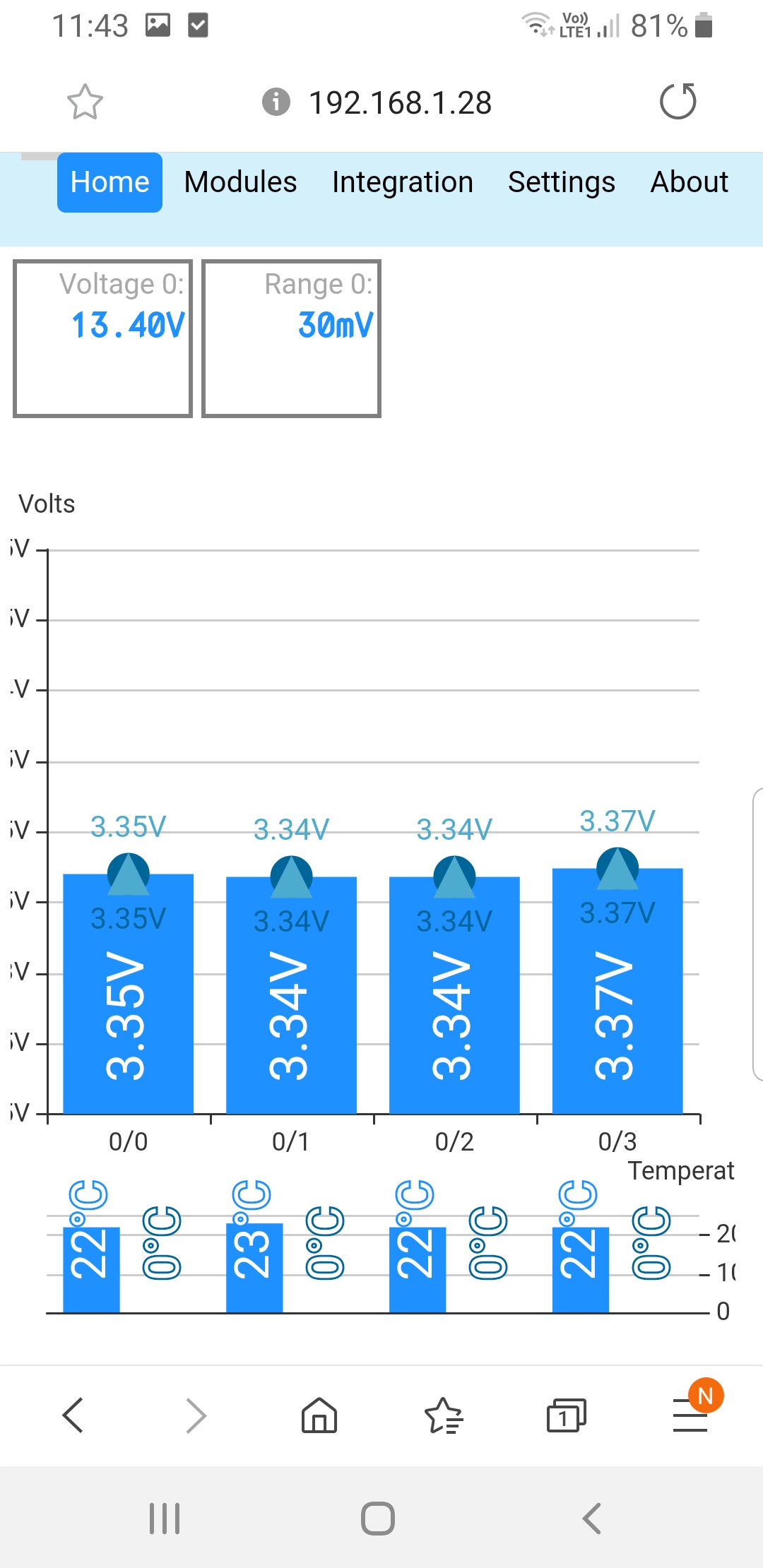
Yes, every thing is working. Webpage, no error and so on. But the voltage on ever cell wont change. If i conect the cells and enter ther real voltage in the settings. Then start to use the battery. The exakt voltage i putt in from start will still show. Nothing change with the voltage.
I cant ounderstand whats wrong. It is the same on every modul and i have 10.
Can you give a screenshot?
There are 3 bits of information on each bar (one bar per battery). High and low. And current voltage. Maybe you are looking at the high voltage? not the current voltage at the bottom of the bar?
If you look at the second tab it’ll show the cell states in rows. Sorry I forget the name of the tab, but it has a current voltage state in it’s own column.
Do the bar’s on the first page move at all?
Ther is no voltage change. Every thing regarded voltage is static.! The voltage thet shows is the voltage i have sett in the settings meny.

Screenshot_20191121-114314_Samsung%20Internet|243x500
Mod - I have pasted the image directly so it is easier to see. You can just paste an image into a post - no need to attach the image file. BPO
You’ve ordered the wrong version ![]()
Don’t worry - take a look at the top of the controller code - you can change the i2c address there and all will be good.
//PCF8574P has an i2c address of 0x38 instead of the normal 0x20
PCF857x pcf8574(0x38, &Wire);
Change 0x38 to 0x20