Because of the type of batteries you use, it seems, I am not sure that you share wires between cells, that is, each cell does not have an independent positive and negative, if this is so, what you appreciate is a consequence already described, on the common negative. When starting to discharge, the discharge cable increases its resistance, modifying the reading of the next cell and causing this cascade reaction.
I think that in Battrium (I’m not sure) they solve this issue with software correction and change in the sampling of the readings, I don’t know very well how they do it, but in DIYBMS you have to use independent cables for each of the cells to avoid it.
1 Like
Thanks! I will do that and test some more 
Be careful, people
a seller on ali express under the name automobile house Store
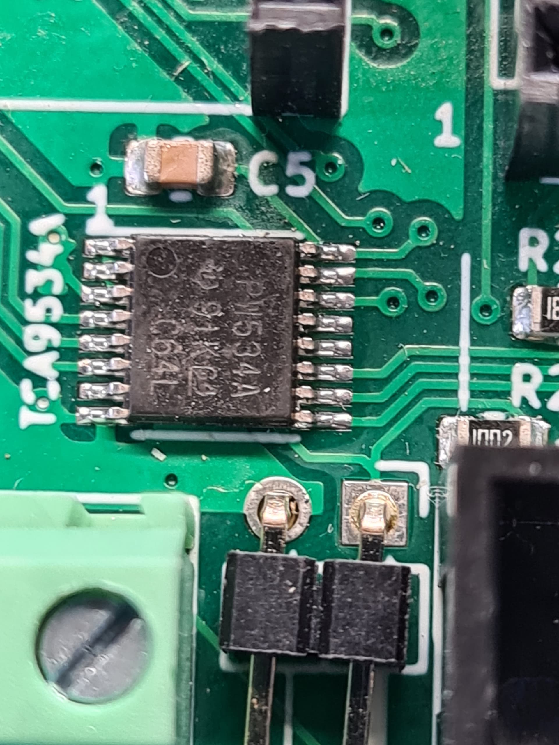
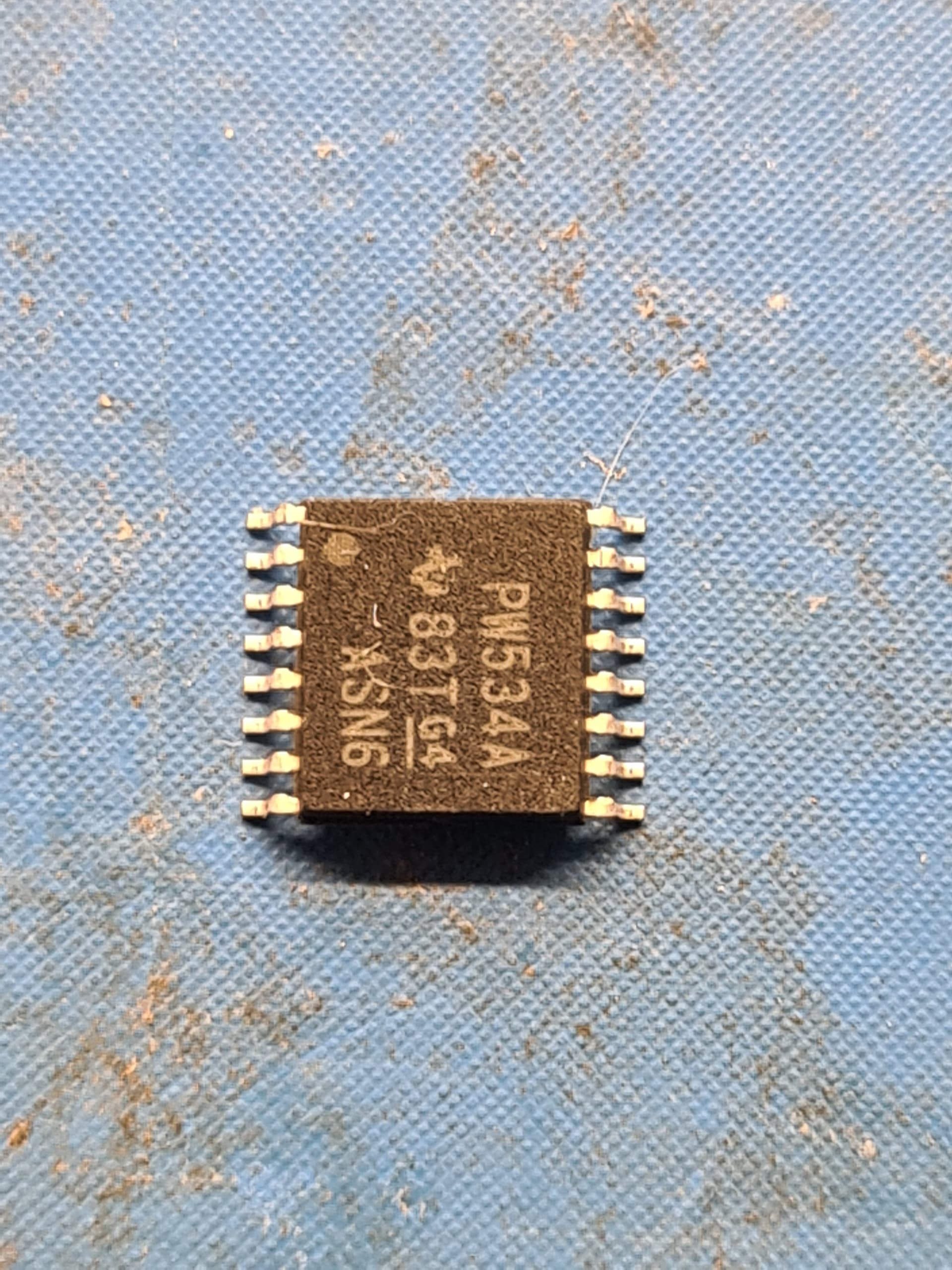
selling fake TCA9534APWR chips, i needed one more to complete a board and they come in 10’s all dont work
what i noticed on orignals is pin 1 is a dimple in the chip and on these fakes its a printed white dot.
I’m very sorry, the truth is that leaving proven suppliers is a very risky sport.
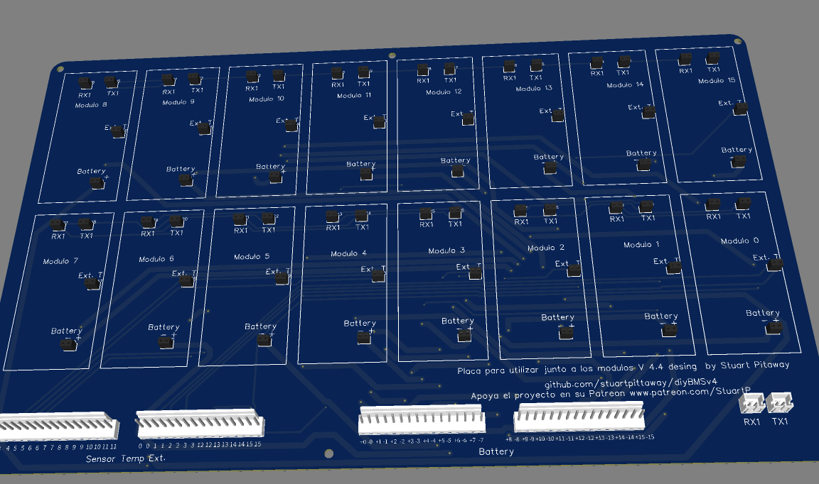
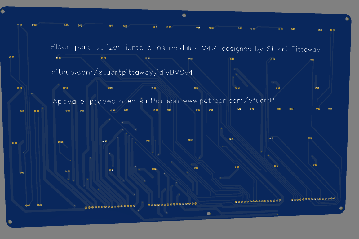
The new version of the board to connect 16 v4.4 modules is already available. I don’t know what is the best way to share it
2 Likes
what is different compared to your old layout?
on the front is a bug with stuarts name
minor changes, correction of labeling in temperature sensors, correction in RX and TX connectors (with the previous model of connector at 90º) the cables were wrong (crossed) I have added two additional holes for fastening in the center (before only in the 4 extremes) and add the correction to Stuart’s last name.
Thanks
I am also bougth that fake chips from same seller. My opinion that is remarked TCA9534. I am solder only that chip to PCB, then run I2c scanner and it found a chip with address 0x20.
Cut PCB lane between 2 and 3 pins and connected 1 pin to a VCC a nearest capacitor. After this manipulation chip start to answer to 0x23 I2C address. Little change in definition “#define TCA9534APWR_ADDRESS 0x38” to 0x23, compile, flash, and voila.
Thanks for the info!
how about the modules software versions? I saw differences in the code.
Do they also work with all controller boards / versions?
In my controller webpage dont setting Bcoef and Load Resisitance not user setting, only displayed default value. What is problem? Module V440 firmware module_fw_V440_attiny841_440_eF4_hD6_l6C.hex controler wemos d1 mini, firmware diybms_controller_firmware_espressif8266_esp8266_d1mini.bin Its good version for setting this options on web interface?
Correct, those settings are hard coded based on what version of the board you are using.
Good morning everybody,
I want to leave here the conclusion regarding the problems I had in my modules (erratic functioning of the leds, communication failures, impossible to program, etc…). I even thought that the problem was with the attinys… So it was like this:
I have 2 controller cards with esp32. One of them is working with the battery that is already in production, connected to the inverter, running without problems for several weeks. The other spare
controller board, I was using to program new modules that I was manufacturing and placing in the new battery bank that I was going to add. Now, for whatever reason I haven’t really noticed yet, all modules programmed with this spare controller board had this erratic functioning. It certainly wouldn’t be because of the esp32 firmware because I tested it with several versions. I believe it could be related to the power supply of this controller board (phone charger…) or any other physical problem on the board or esp32.
Now I’m programming all the new modules with the controller that is already working and everything is working fine: I already have another battery bank with +28 working modules! I emphasize that the modules that gave problems, even if you program them again with the correct controller, the problems are not solved. This could be related to an incorrect programming of the fuses, which even programming again does not allow correction.
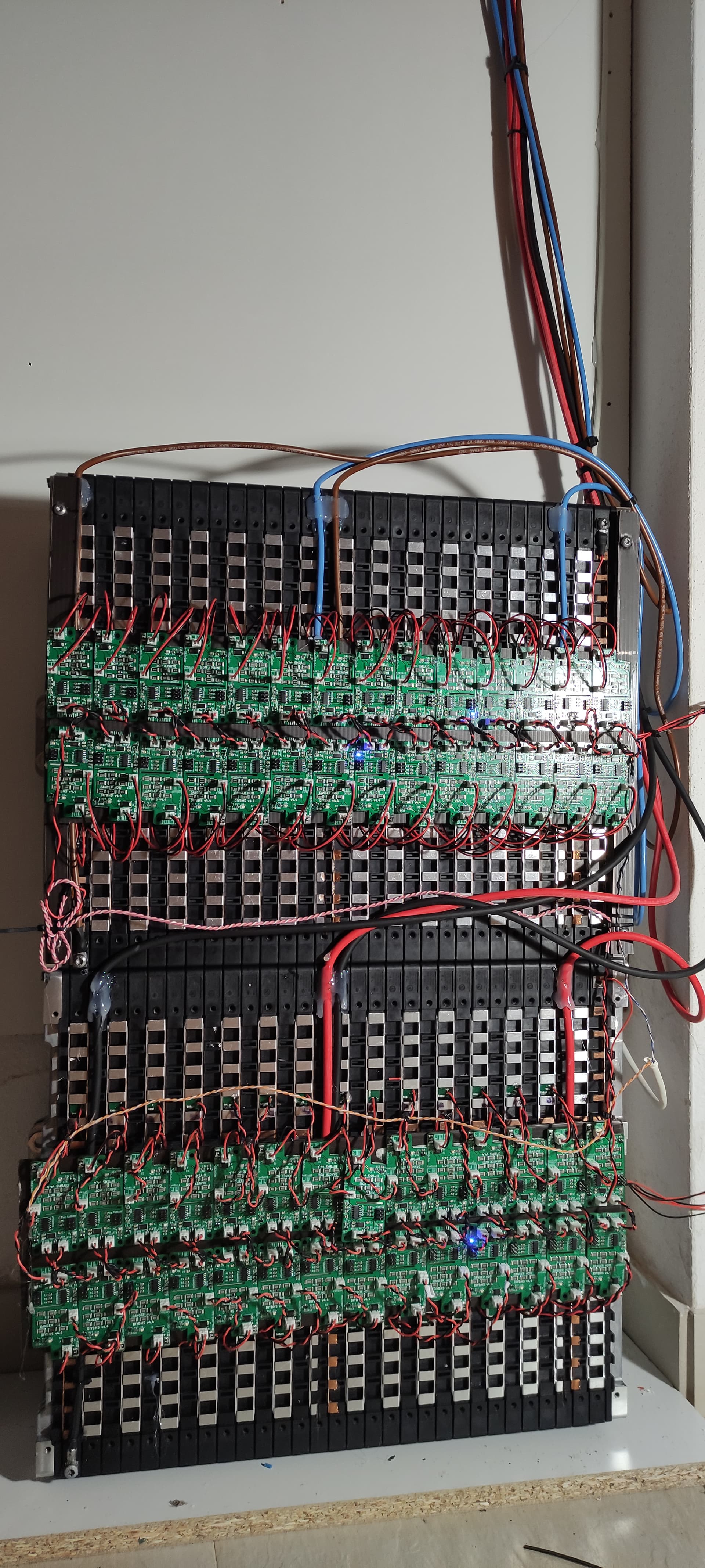
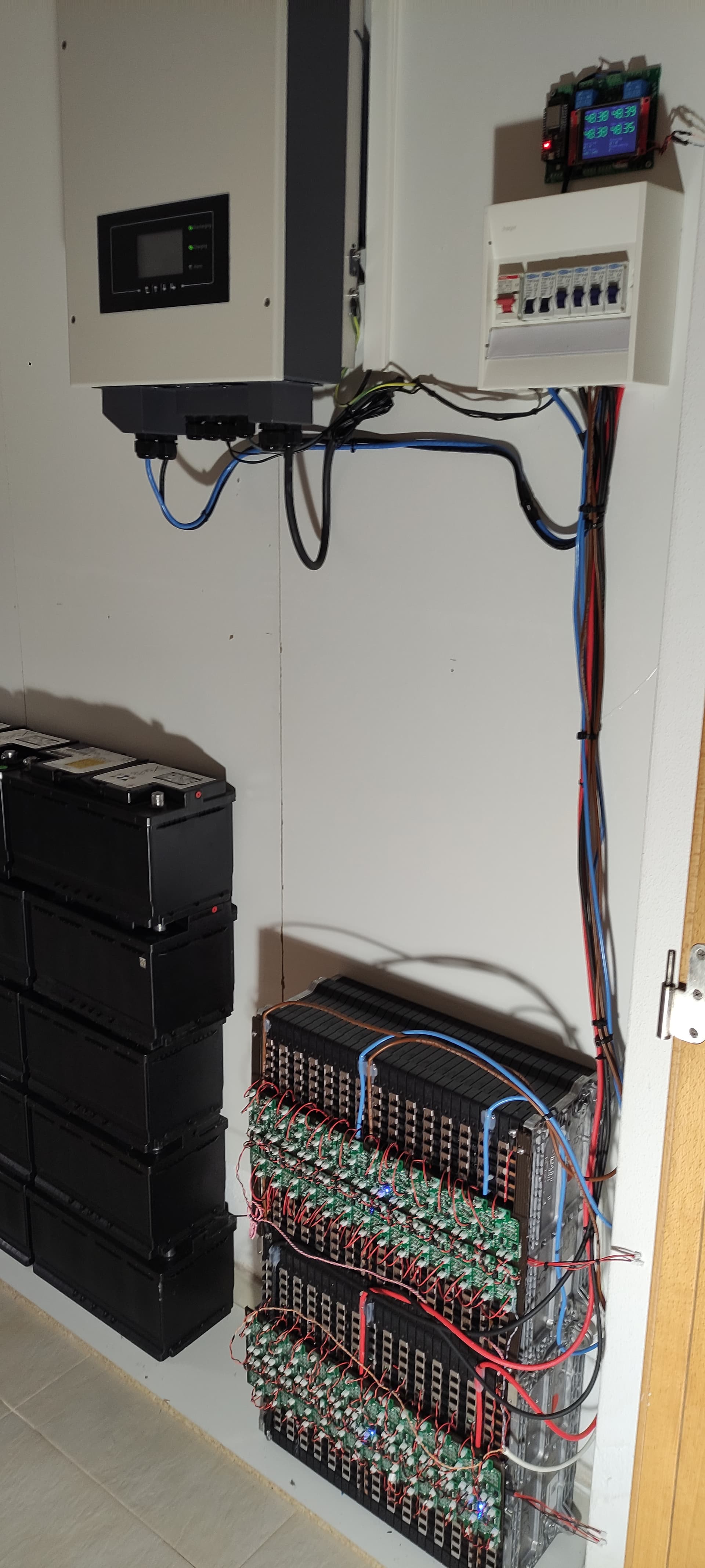
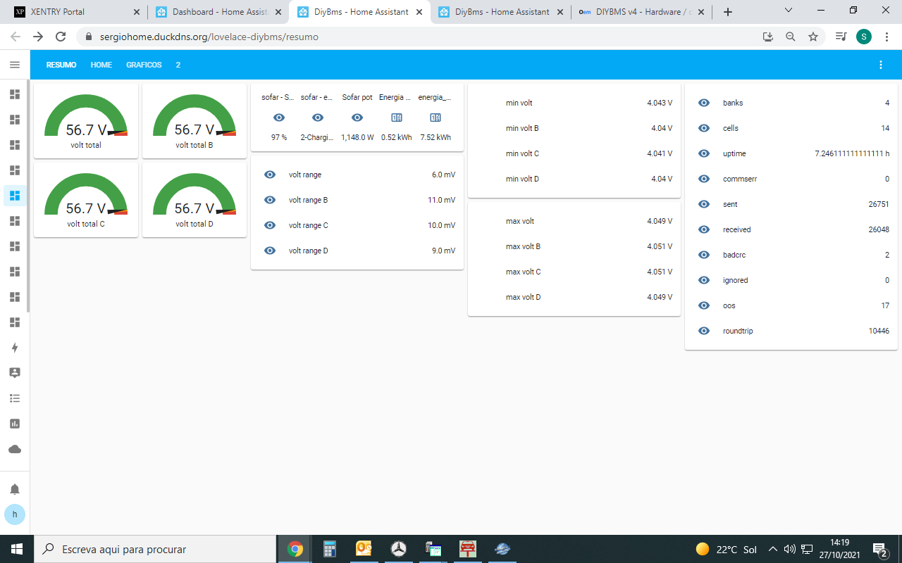
So thanks to everyone who helped, here are a few more pictures of the system working.
My controller have rising error counters with long cable (about 1 meter) from last module to esp32 pcb.
Powering ESP32 controller directly from microUSB gave less errors but not zero, about 8-10% comparing to packets send.
Now i am using short RX and TX cables and connect power from USB adapter to a screw terminal. Packets sent: 530002 O.O.S errors:72 CRC Errors:71 All modules Bad packet count: 0. But screen and status LED is not visible.
what is your round trip time with all this modules?
Hello Dan, 10400
10second response time isnt that too slow?
56 modules… all in series, not much to do. But in practice, it works very well and I don’t see a great need for more speed, because each module is autonomous in balancing.
it depend on the battery that is used, for my lifepo4 3sec roundtrip is sometimes a little to slow because the voltage rises and drops very fast