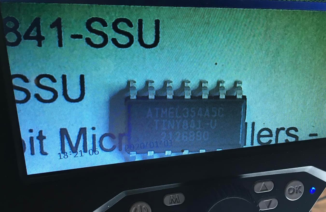
then that is your problem
you need ATTINY841-SSU
Gareth, are you sure?
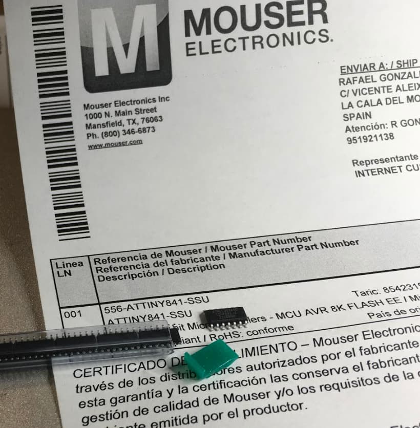
Despite it says TINY841-U on top, the reference I bought is ATTINY841-SSU, here is the link: https://pt.mouser.com/ProductDetail/microchip/attiny841-ssu/?qs=HVbQlW5zcXVaBIh573n%2bhw%3D%3D&countrycode=DE¤cycode=EUR
Was there a mistake of the supplier?
sorry i just checked mine and they say the same  there must be something else missing from the board casuing them not to flash
I have also checked previous ATTINYs and they are all labeled as -U. What happens is that I have already told the Mousers that they were wrong. Anyway, I will clarify the misunderstanding with them. Thanks.
Thanks for the answer. Stuart
I will buy AZ432ANTR-E1. I hope it will be better.
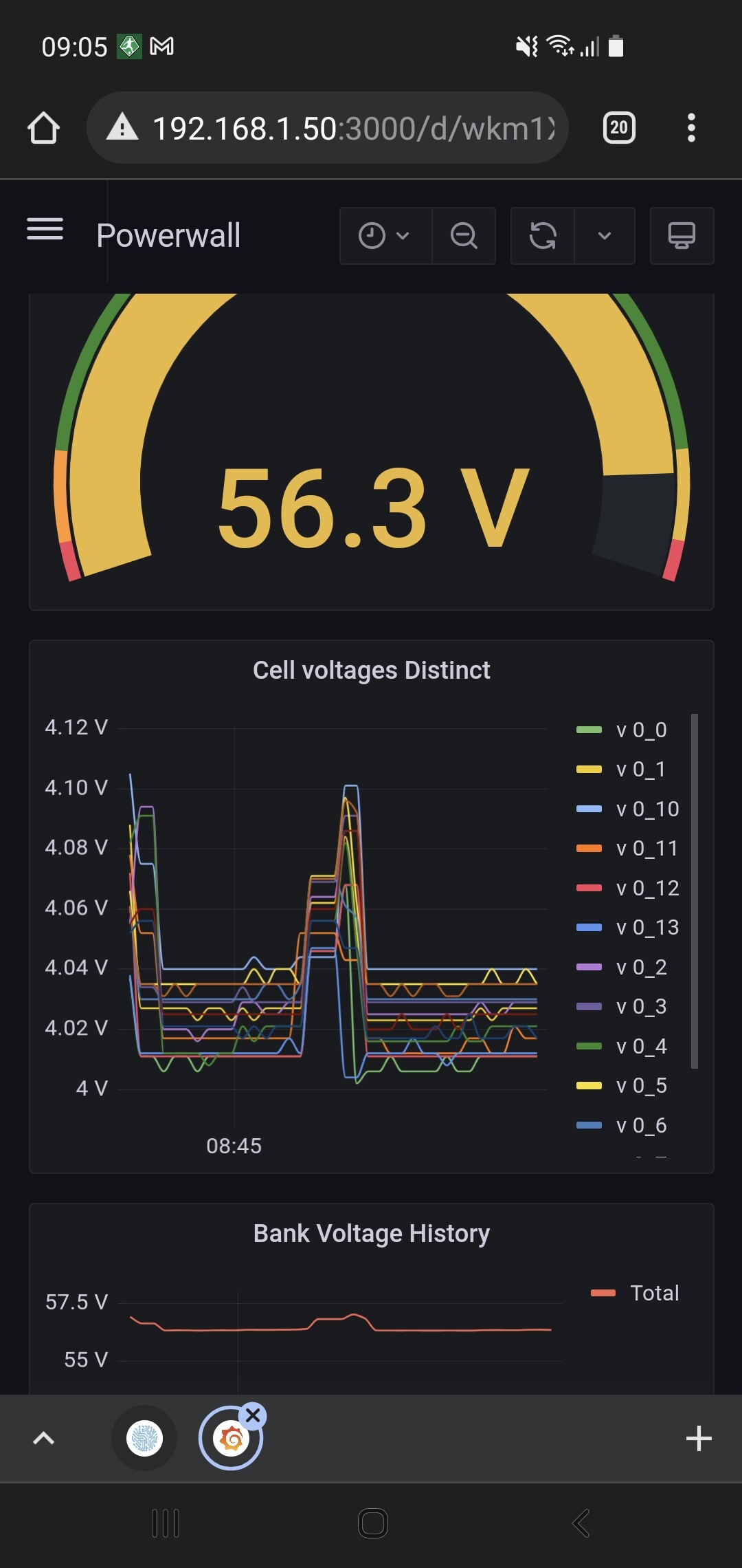
I want to know how does module measure voltage?
How does voltage from battery go to the Voltage Reference? I don’t see connections in the schema.
Thank you. ^^

The reference is powered from one of the pins on the attiny chip. It switched this on and off as needed to save energy.
I’m having problems to connect the controller to my Victron Venus (raspberry) through Canbus. I bought a recommended USB adaptor.
Now I’m trying to diagnose where’s the problem, as it can be:
- Compatibility of this adapter with Victron VenusOs
- Missing misconfigured driver
- The CAN chip being bad.
I had problems with the can chip shortages and finally accepted an offer from a extortioner, and could be that those chips are a bad batch or simply wrongs. They are the right and exact model though.
I need to know what part of the communications the following messages are referring to. ESP to CAN chip, CAN chip to USB Adapter, or simply the host not answering.
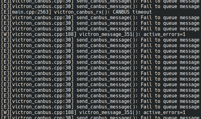
The CANBUS adapter has tx and rx leds, but those hadn’t lit just one time.
Any help would be greatly appreciated.
PS: The adapter is this one: https://www.inno-maker.com/product/usb-can/
1 Like
I’m preparing to build some myself, and in reading this, and looking for these units, I looked throught the datasheets to find out what the difference is between “-SSU” and “-U”.
Looking at the datasheet for “Attiny841” and looking in the ordering information, there’s nothing called “-U”. I think the the “SS” in “-SSU” refers to the package type, and since it’s easy to see if it’s a SOIC (SS), or QFN (M), there’s no reason to print it on the chip (at least I think that this is the case - please don’t hesitate to correct me if I’m wrong, I just can’t find any Attiny841 datasheets where “-U” is an option).
We already clarified that it was a misunderstanding, ask for your ATTINY SSU and you will not have any problem
Hi Fam, So after ordering my new parts I am running into some availability issues for some of the chips…Some of which I simply cant find. So do Any of you magnificent folk have any available?
-
CA45-A010M226T 8
-
AQY212GSZ 4
-
TCA6408APWR 2
-
TCA9534APWR 2
-
TJA1057GT/3J 2
The above Are parts I just cant seem to find, but Im also looking for the below, so If anyone has all of these, Id greatly appreciate being able to buy everything from you.
- ATTINY841-SSU 20
- ATTINY1614-SSNR 5
- ADM2483BRWZ 5
- LM5009AMMX/NOPB 6
can anyone tell me if I can replace these with something else ? A quick search tells me I can get alot of capacitors with these (22uF ±20% 10V 3 Ω @ 100kHz -55℃~125℃) Characteristics, but seeing as Im not sure, any response would be great.
Hello guys,
I dont know if this post end up in the right place, hope so.
is there any table that shows which controller boards are compatible with which cell modules?
And also which module firmware is compatible to the controller version?
With the growing number of different boards it gets confusing.


all controllers control what ever versions of the cell modules it doesnt matter if its the v4 or the 4.2 controller they work with all modules even mix and match
I just got my PCB’s from JLCPCB the other day and on trying to build i think that they reversed the SD card holder.
Is it critical or should i still be able to power up the system and get basic testing done.
The other thing i noticed is that the SD card seems to be slightly bigger than the end of the SD card holder so it seems that it wont insert (Ignoring the holder being around the wrong way)
Thanks
Davey
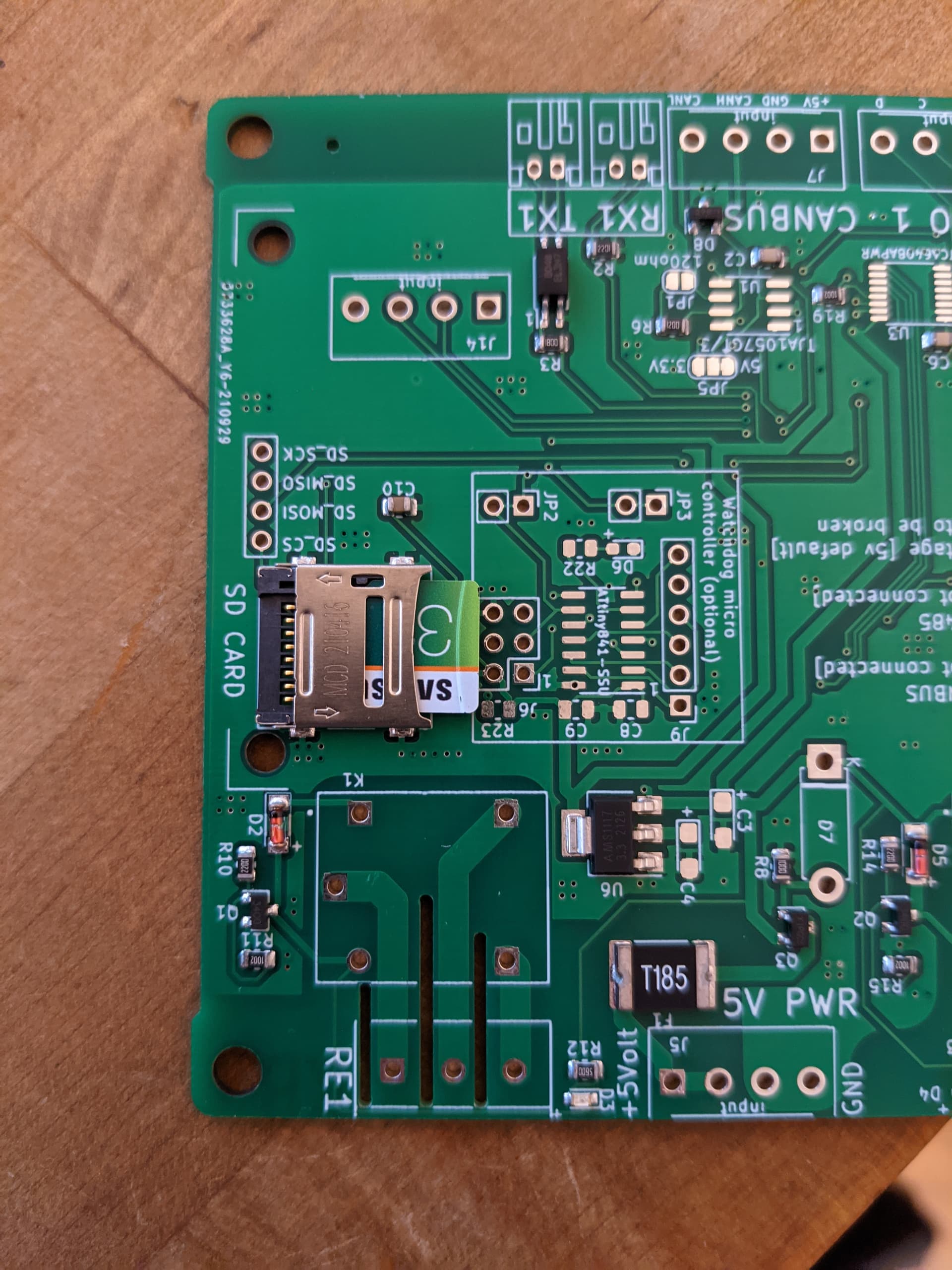
see the little arrows on the sd reader slide it that way and the metal bit flips up, then place the sd card inside and then close it back down and slide it back again
Well i feel stupid  it took a lot of force to get it to open at first. Thank you.
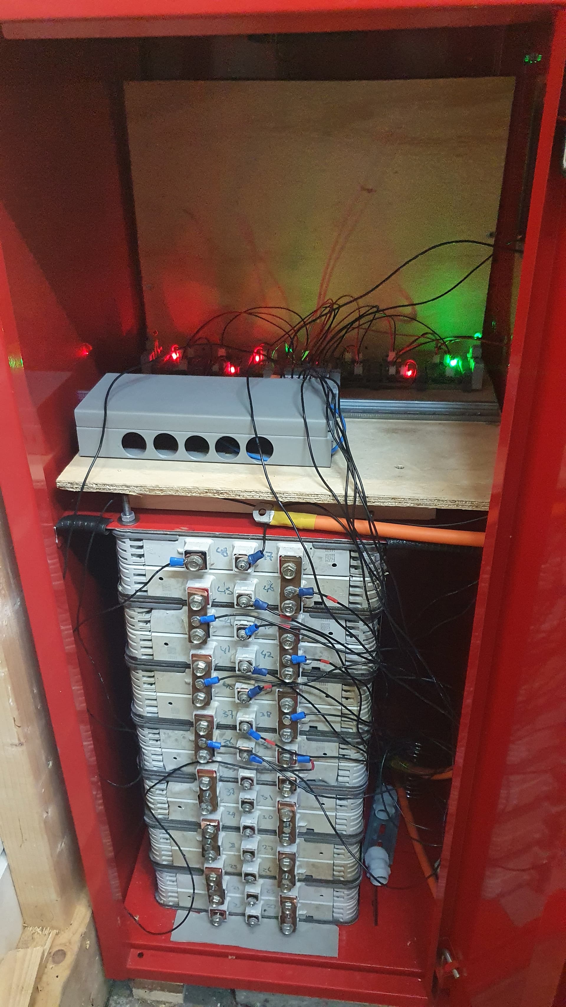
In testing i found something i did not encounter before; when my modules start balancing the voltage of those modules but also the others seem to be rising. Although the cable from battery to module are 75 cm (0.5mm²) i have had longer cables and not this problemen. The cables go from battery to pt 2.5 blocks and then to module. I have twisted positive from one cell to negative of the next cell. Should I use thicker cable to the pt blocks or do I need to use dedicated cable per module?
1 Like
I found this component finder. It helped me to locate the LM5009 (which I want to repair to a friend) although later I could not buy them in Arrow (USA) because they only sell to Companies that can buy without VAT and I am a natural person, maybe I can help you to locate some of the components that are costing so much to obtain.
1 Like