Hey Stuart. I am a Canadian in Turkey leaving in a few weeks in my boat. Will be heading west and won’t be able to get post for probably 3 months. I have a house battery 8s4p lifepo4. I am currently using a Daly BMS. 2 yrs old no settings or stats visibility. And if that’s not bad enough it let a cell drop to 2v before shutting off.
I ordered some other custom (not diybms) jlcpcb 6 weeks ago and they are still not here. I am wondering if you have a current 4.4 controller and modules that I could buy from you or someone you know and have them shipped to turkey.
well thanks to a poster above, I found / remembered aliexpress and it looks like the parts are available. Be aware these are only parts missing from placement on the bom list when submitted to jlcpcb. I got the boards yesterday so haven’t really gotten around to listing rest of the parts for the shunts / controller plugs and such (the ones that arent listed for placement (like the shunt itself).
But if you want the list and the boards I can make a package deal (like everything it cost essentially) and you do some assembly.
Remember these are diy projects so, doing some of it yourself is kind of a requirement.
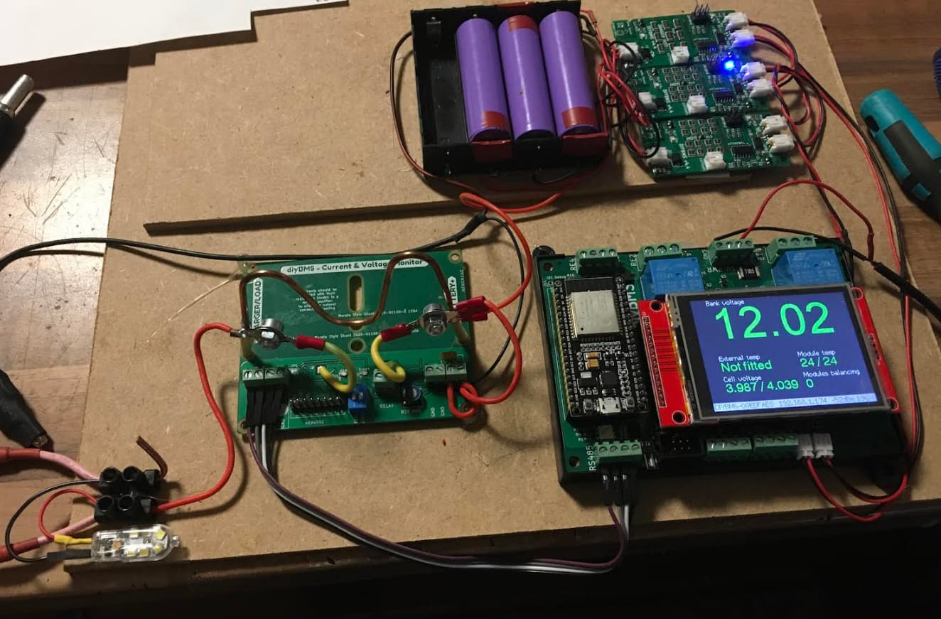
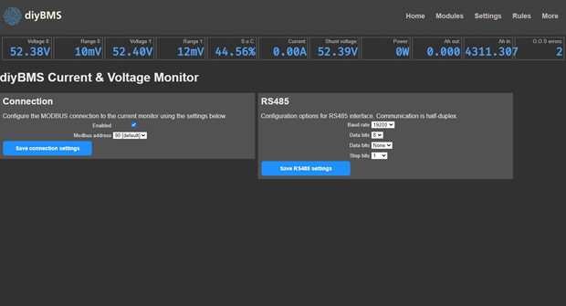
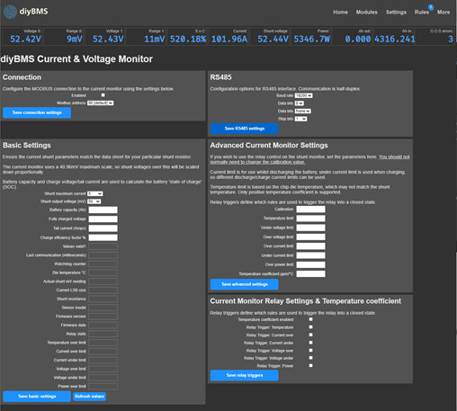
We start from here.
The shunt has a 500A 50Mv Shunt Resistor installed
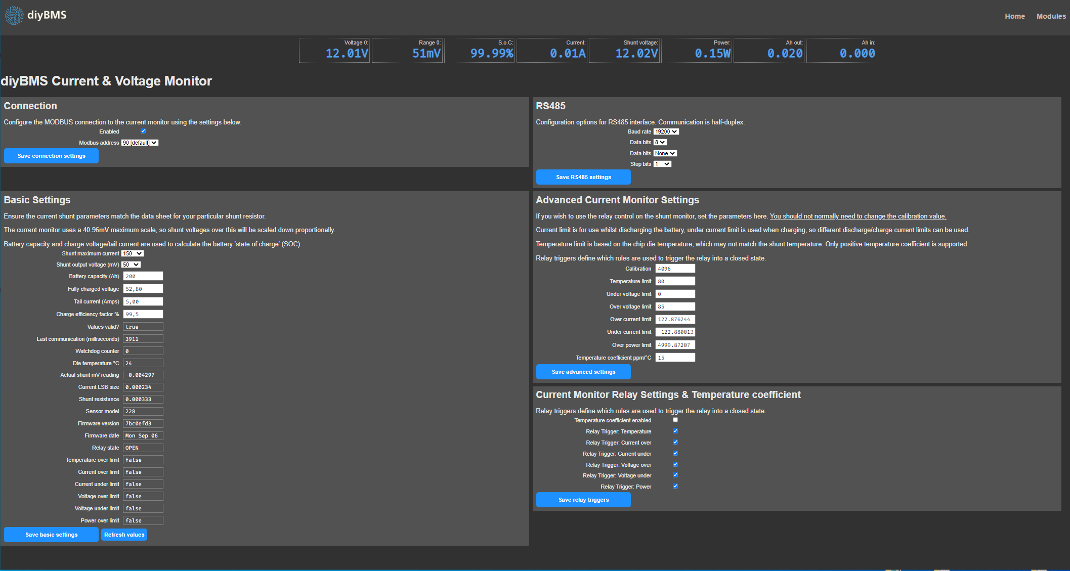
When I open the shunt configuration screen, the basic parameters option does not always appear.
If I activate the connection, I start to have data from the shunt but it does not mark any current or power, and the option of the rest of the configuration does not appear
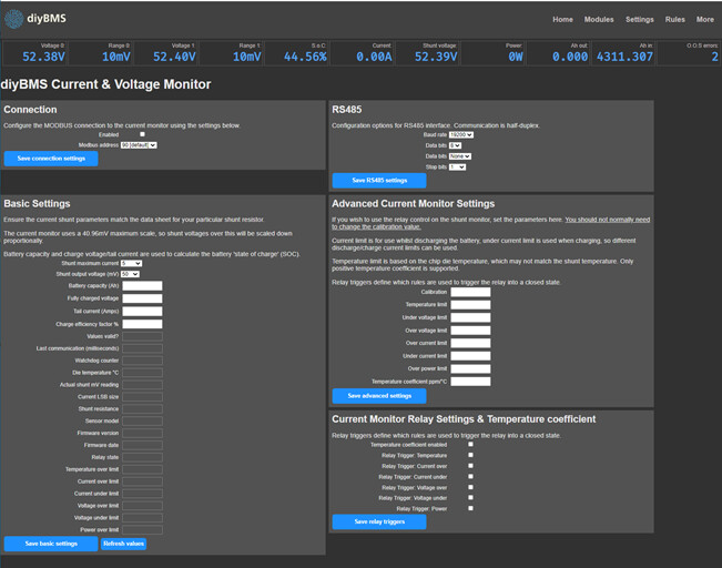
I open the browser again and now I have the option, but always with this data:
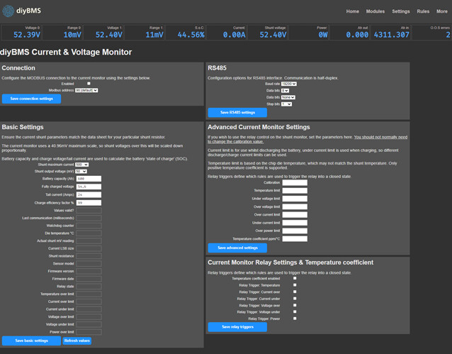
When I try to record this data that is what I understand is the proper configuration:
And save them
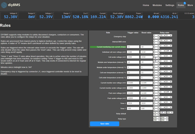
I start to receive data, but wrong
Example:
Current 150.26A when the Victron System tells me about 21.5A
And on the other hand, the SOC goes from 44.56% to 520.18%
While obviously, the high amperage alarm is activated
On the other hand, if I reopen the shunt configuration, instead of presenting the recorded data, it returns me to the default Shunt data of 5A and 50mV
What could Stuart be going on?
I want to start communicating the BMS with Victron, but I can’t do it until I have reliable data through the Shunt.
I have been able to verify it, I have restarted the shunt and after a few green flashes, the red led remains fixed and the green one flashes every 5 seconds. But I don’t know what it can mean
I have tried another shunt and I have the same problem, the configuration values are not saved, I suspect it may be a firm corruption problem, tomorrow I will try to install the shunt firm again (latest version and we see results) .Thanks Stuart
new here, would also like to thank Stuart (as well as all the others building/testing/modding!) for this brilliant work!
Learnt about diybms less than a week ago (already checked electrodacus and chargery), spent the best part of the last 3 days “studying” - read the whole thread (from post1 all the way to post3953 ) and lots of other threads spawn from here.
Planning to upgrade my motorboat service battery set from 4X6V Trojans cart batteries (225Ah@24V) to 8 EVE280Ah LifePO4 cells in 8S configuration.
Setup is fully Victronised so keen on getting both the MPPT and the MultiplusII to be instructed by the Raspberry Pi running VenusOS to stop/start charging/inverting. Real estate limited on a 43ft boat so only have two 300W panels to be replaced with 2 370W ones (same size), a 8kva diesel generator that I try to avoid using if at all possible and main engine alternator. Nevertheless, 95% of charging done by solar.
I’ve setup grafana already and check all boat related data remotely, so cell values will be added (via the victron posting the data received via VE.CAN from the bms)
I have some experience with pcbs (have done a couple of batches with JLCPCB in the past for some boaty NMEA2000 teensy based boards) so plan is to built a batch of 10 modules for the cells as per Jau et al design (DIYBMS for Lithium Iron Phosphate battery cells (LiFePo4) 280aH - #19 by Michaelillingby) and then wait for JLCPCB get their act together to built a ESP32 controller board. Cells ordered this week, so will be here in Greece hopefully sometime in January, gives me plenty of time to sort out a few issues I have -mainly placement and a way to switch from lifepo4 back to the standby trojans if a need arrises - extra relays on controller board will be handy here.
Actually, quite keen on getting my hands on a controller board and test the rpi comms as I have to figure out how the canbus protocol will work with the rpi. So closing this first long post with two questions:
Anyone have a new format built board that is going spare in Europe? happy to buy it and do my rpi comms tests earlier!
Have a couple of ESP32 NodeMCU going spare from other projects, are they compatible with the new controller board?
Indeed, I have tested in the test panel with a new firm for both the controller and the shunt and everything is perfect, now I will have to reprogram the shunt installed in the battery. Thank you all
Yesterday I put in operation a second battery bank and experience some issues with external temperature sensors. Maybe some can explain why is it so and advice me what can I do.
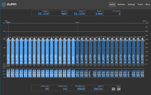
The 1st battery bank is working fine. It has v421 cell monitoring boards and external temperature sensors were hand soldered using thermistors from aliexpress. All values from external temperature sensors are shown correctly (bank 1 on the screen shoot).
The 2nd battery bank has issues with external temperature sensors, other functions are ok. It has v440 boards and for external temperature sensors a snap-off part of the module board was used. The readings is complete mess: half of the sensors are not recognized by the module, some showing strange values (like -38) and only a couple shows something reasonable. It is a bank 0 on the scree shoots.
Any ideas? I do not think that I was able to solder a separate thermistor to wires, but made so many mistakes by soldering a small pcb…
And a 2nd question.
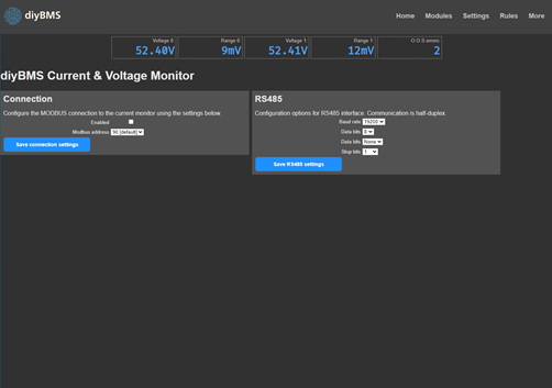
After a second bank was added a BMS controller shows me 2 warning messages: @stuart should I expect any issues here? I thought that the cell modules are only different from hardware point of view, but have the same “logical” functionality. Could I use it as it is : v440 for Bank 0, and v421 for Bank 1, or must all cell modules be the same within one BMS controller?
Ok, I need to check it. Because the v421 boards and the Controller were flashed like a month ago, and v440 boards - yesterday with another/spare controller and have the for sure the latest version.
They were ordered from JLCPCB without any changes from my side. Since attiny, load resistors and D1 were out of stock, they were ordered separately and hand soldered.
This I do not know, because I put the sensor in the middle of the 18650 pack under the heat shrinking sleeve, so they were snapped off long ago, long before the module boards were completely soldered (attiny, d1, resistors)
My plan for the evening is to make one more temperature sensors, the same as I use by v421 boards, and test it with all v440 boards
That I have figure out during the test =)) and made another sample temperature sensor from a spare board (a snap off part of it).
@stuart
Looks like there is nothing wrong with boards, because with that additionally built sensor they show correct temperature. But it is really strange, that all 14 snap-off sensors are faulty… Maybe I haven’t filed the snap-off part good enough and there is some additional resistance or short between traces…
Will redo all of them…
Unfortunately I have found one more issue after a day of operation. It looks like there is some communication issue between module 5 and 6.
This is only overnight
Communication cables are short and good twisted. The one between modules 5 and 6 has been changed yesterday evening and “Reset counters” done. The screenshot is from today morning.
Any idea where to look for a failure?

 ) and lots of other threads spawn from here.
 so keen on getting both the MPPT and the MultiplusII to be instructed by the Raspberry Pi running VenusOS to stop/start charging/inverting. Real estate limited on a 43ft boat so only have two 300W panels to be replaced with 2 370W ones (same size), a 8kva diesel generator that I try to avoid using if at all possible and main engine alternator. Nevertheless, 95% of charging done by solar.