Stuart,
I checked the material with the list I used from your github.

Just to clarify, the D2 diodes are correctly positioned, that is, with the dash to the right.
As a curiosity, on some of the cards that aren’t working well (50% of them), I can’t even reprogram the attyni841. It gives programming failure.
Sorry if I’m posting too many comments/information.
Thanks,
Sergio
Ok, JLC have rotated part D2 (diode) which sits on the input to the module.
The “stripe” of the diode should be pointing to the right hand side of the board (toward the K marking). It looks like JLC often switch that part around in orientation - very annoying!
If you can’t program the ATTINY, then it looks like either faulty ATTINY chips or bad soldering of them.
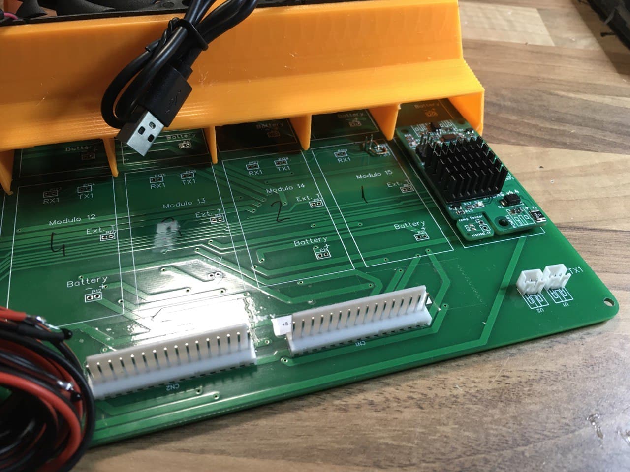
Evolution and improvement I have thought for the next group that I am going to mount of 16 that since the height of the fan support gives me for it, or I can place heatsinks on the resistors, although I will no longer use the connector system to puncture the boards but I am going to solder the V4.40 modules directly to my board.If any fault occurs, replacing it is not as simple as punching it out, but it is not particularly complex to desolder the eight pins and solder a new module.
1 Like
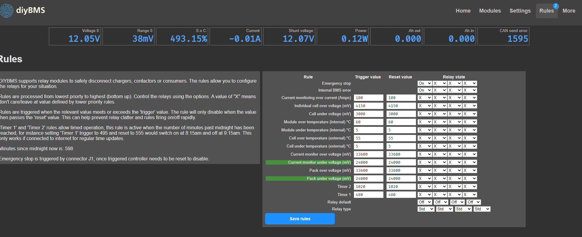
That looks like it’s telling you that 2 rules are currently triggered (as shown in green).
Just a quick one. I notice that JLCPCB are out of Tantalum capacitor CA45-xxxxx, since this seems to be a polarised variant, could a multi-layered ceramic be used instead?
yes is this , thanks
I found that the volt values shown on the screen did not match the ones i measured with the multimeter. I’ve tried calibrate. But when the volt changes The values are not matching again.(board v4.4) (esp8266)
I use a 470 ohm resistor instead 510 ohm i don’t know if it’s related.
How to fix it? Thanks
Correct
How accurate is the multimeter?
Have you tried the latest module code on your modules?
You should be able to get a resolution of 0.004V on the readings.
The multimeter has an accuracy 0.00
I use avrdude program with hex file “module_fw_V440_attiny841_440_eF4_hD6_l6C”
The problem is when i connect module with battery volt values shown on the screen did not match with multimeter (multimeter:3.28 V / screen:2.615 V). So I measured it with a multimeter put that value into the calculator box and click calculate. After that the values match.
I setting bypass threshold mV configuration at 3200 mV (LifePO4).Then board still heats up.The volt value of the battery I measured with a multimeter is 3.20V but the screen shows 3.310V
I printing pcb by myself.I don’t have some components.
- I use a 470 ohm resistor instead 510 ohm (R14)
- MAX6001EUR+T instead AZ432ANTR-E1
- MF-MSMF150-2 instead mSMD150
I am very interested in diy bms but I’m not very knowledgeable about electronics.I’m trying to study how it works.I don’t know what’s wrong i do.
Thank you very much. Stuart
 Sorry I’m not good at English.
are the cooling fins necessary? is just the air from the fan not enough for cooling?
You’re English is fantastic!
Not using AZ432ANTR-E1 will be the problem.
That component sets the accuracy of the whole voltage reading.
Good morning,
I still have erratic problems in my modules. In the last modules I made yesterday, I used diybms esp32 firmware with firmware from 06/22/2021 to program them, as this is the firmware I have in my other 28 modules that have not had problems for a month. I replaced to the cable i used to program.
After programming and plug on the power, sometimes it turns on the bypass red led right away and starts to dissipate energy in the resistors, other times it does not turn on any led, other times it doubles the blue led only once, other times it works well for 1 minute and then it stops…
I gained courage and even sent an email to mouser. I’m sure they’ll think I’m crazy (and maybe they’re not wrong) and won’t even reply to my email.
Anyway, I have a friend who has a professional electronics workshop and I asked him to make 2 modules, ie weld the attinys into 2 modules v.4.40 using a correct method, I think he uses an oven. Then I put the result here.
Thank you for your help.
Sergio
Sergio, I will have soldered more than 250 attiny in modules. I am not a person with a great experience in soldering, and although occasionally some solder presented deficiencies (some pin not connected) I never had problems for having overheated the Attiny. Let’s say that to get to this point you should have increased the temperature of the soldering iron and / or have maintained its contact with the attiny for a long time.
If, as you say, the Attiny allows itself to be programmed, the problem may be elsewhere unless the bad luck of the solder caused the ATTIny contacts with a defective solder to be curiously the ones that do not intervene in the programming and if in the reception of voltage sensor data, etc. I would tell you to go over all the welds or even check them carefully pin by pin with a magnifying glass.
1 Like
Stuart, i want to thank you for all your work what you did for this project. In last 3 month i am sucessfully build DIYBMS for my bunch of cells.
16 x 240Ah LiFePO4 cells.
Charger Flatpack2 48V 2kW
Inverter Mean Well TS-3000
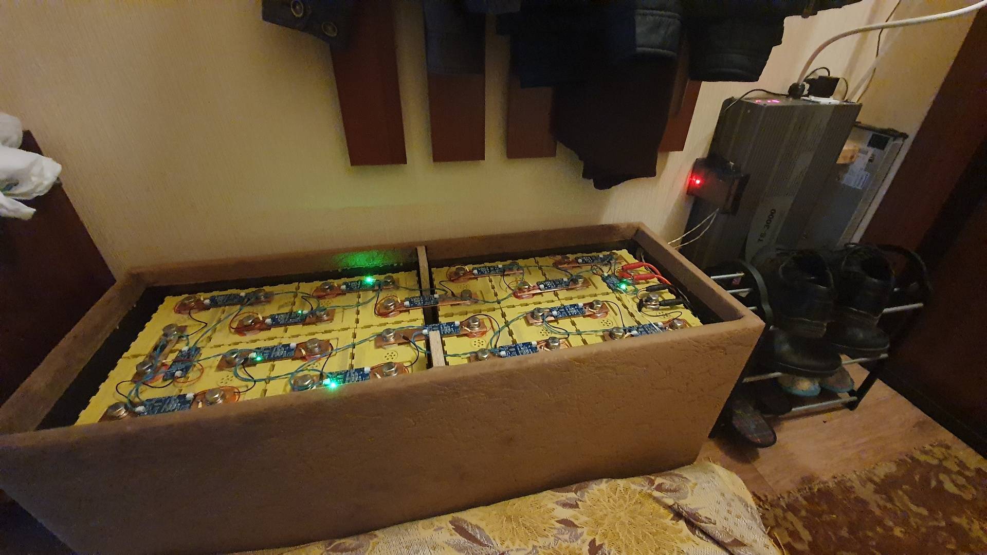
Charger have CAN bus, and now i studying how to get status messages from charger.
It would be a great if you can add support flatpack2 charger to DIYBMS.
Rafael,
you are absolutely right. I’m also not very experienced in soldering, although now, due to this situation too, I’ve been forced to get some practice. The curious thing is that I made 28 modules about 5 weeks ago and I didn’t have any problems (initially apart from the poor quality serial communication cables) and until today, they are working very well. Right now I’m even using pcb boards from that initial batch, to rule out any defect in the manufacture of the boards.
I don’t really believe it’s related to soldering, but I’m waiting for them to deliver 2 modules whose attinys were soldered in an electronics laboratory, so that I can test and rule out the possibility of a soldering defect.
We will see…
Thanks
sergio
what does it say ontop of the attiny chip its not the U version is it?
Yes it is. It says TINY841-U on top!