hello sir is there any alternative to (Analog Devices ADUM1250ARZ)
Hello, the adum chip is from the old V3 design which I won’t recommend for new builds. Use the V4 instead
@stuart , do you know which chip controls the rs485 on the 4.2controller board? ive built a shunt and its working on all of my controllers but not on the prototype one that i originally blew up, so just wondering if it took out that chip too but not sure which is the one.
thanks
also would it be ok to offer 3 fully built controllers and shunt boards for sale as they are spares i only needed to build 2 for my projects but thought id just complete all the bits on the others (minus the actual shunt on the shunt boards) just to recouperate costs for building them.
thanks
1 Like

Hello, no problem with you selling spare boards, think people will be grateful for them given the chip shortages.
1 Like
thankyou Stuart, do you happen to know which chip controls the rs485?
also for people looking to buy my spare sets NOW SOLD - DIY BMS v4.2 controller and shunt board fully assembled UK England
thanks
1 Like
Hello @stuart ,
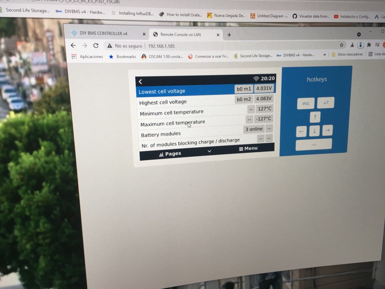
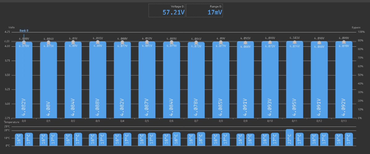
Recently I have spotted some strange behavior of my BMS - some role has been triggered even though all the cells are Ok (voltage, temperature are fine, within the limits). It is not the first time, and has happened previously, but back then I thought it was because of BMS internal error rule (previously I had issues with communication, after your recommendations now there are almost no communication faults).
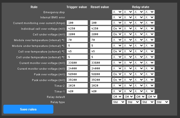
Can you please have a look at screenshots below and let me know which exactly rule it was, and probably then we can figure out why it happens and what to do to avoid it in the future, because it is a bit disturbing, since I have a shunt trip on my MCCB and every time BMS switch it off I need to manually activate it.
And one more thing, I have tried to use relay in a pulse mode, but if I change the Relay type to Pulse, it just immediately change its state (work like an inversion: in Relay default Off, it would be immediately On after applying the change, and vise versa). Do I misunderstand this feature (I thought it should activate a relay in case a rule is triggered just for a second or so, and then deactivate it back) or is it just not working as planned?
Many thanks in advance!
data_20211009.csv (373.0 KB)
It doesn’t log which rule triggered, but I suspect it triggered very quickly and then cleared.
The pulse output should enable the relay for about 250ms then switch off again. Not many people seem to use this and I think there is a bug with it.
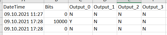
I thought the field “Bits” in the output_log file shows which rule was triggered…
It is however, I little bit disturbing, a 3rd time in a couple of weeks and problem seen with the battery pack. Once I have already suggested to add a delay for triggering a rule, maybe it would reasonable to implement it? Like:
Option 1: separate configurable delay for every rule
or
Option 2: separate configurable delay for every relay
Then such “false positives” could be eliminated.
I also do not use the pulse output. Just tested it and saw some strange behavior.
The bits are just a dump from the tca6408 chip, not the rules.
1 Like
Good morning, maybe this has already happened to someone:
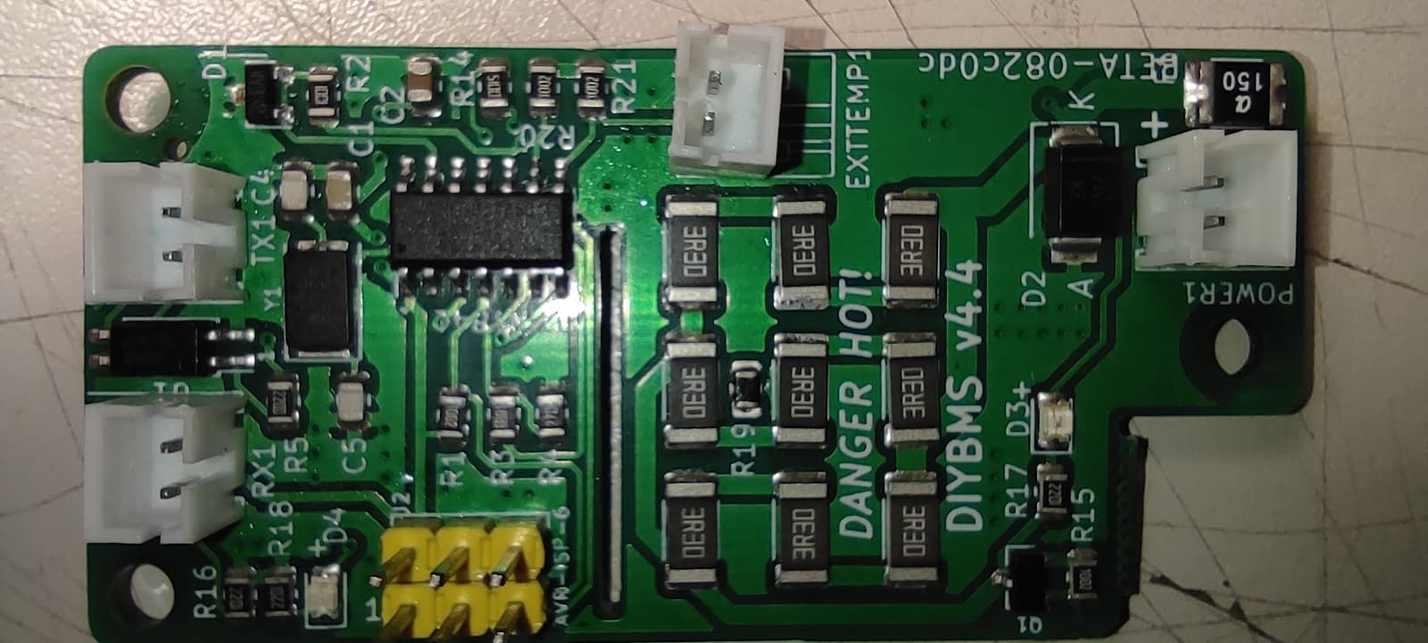
I have a 28S1P battery working with 28 diybms v4.40 modules. Everything is working fine. However I ordered more pcbs from jlcpcb and attynis841 from mouser.com to add a new battery to my system.
This time, I’m having problems in most of the modules: sometimes they don’t communicate, other times they don’t even light up the blue LED, other times it lights up once and never lights up, other times the LED lights up erratically… How I ordered a lot of boards and attynis I’ve been making more modules and trying to figure out what I’m doing wrong.
I can’t reach any conclusions, I’m even thinking that this batch of attynis has a problem. To solder the attyni I am using a small iron without temperature control, but taking care not to overheat the pins of the attyni. In programming, it always goes well, I’m using the version of 10/05/2021.
Is it too much temperature that’s damaging the attynis, even though I haven’t had this problem before?
Can someone give me a tip or have you had a similar experience?
Thanks

Strange behaviour is often the result of not programming the attiny fuses.
Are you using the diybms controller to program them?
Stuart, thanks for your attention.
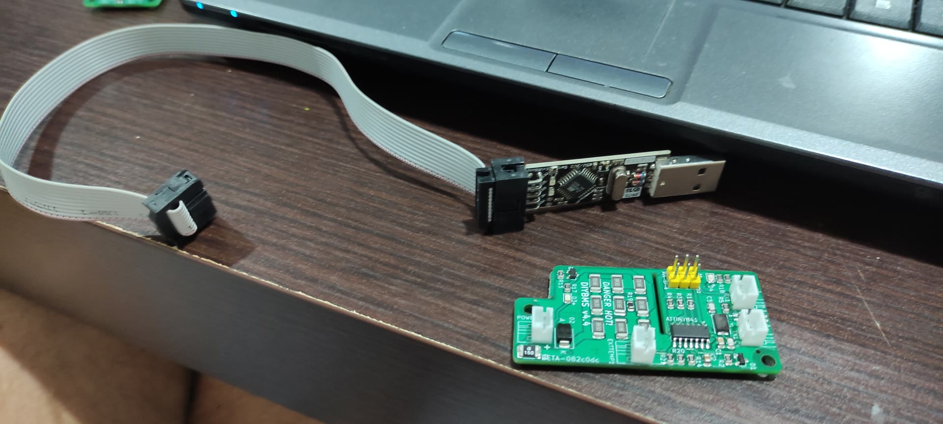
Yes, I am using the diybms esp32. I’ve always done it that way in the past, never had problems. Do you think I should try the programmer on the photo? What program do I use?
Thanks,
Sergio
hi Fam
I ordered my v4.21 a while back , programed the attinys and haven touched the project since. I got back on it yesterday only to find that visual studio or platformio, in its wisdom has implemented updates.
While attempting the flash the d1 mini, Im getting these errrors that point to dependancies in places I cant trace.
xtensa-lx106-elf-g++: error: unrecognized command line option ‘-std=gnu++17’
xtensa-lx106-elf-g++: error: unrecognized command line option ‘-std=gnu++17’
xtensa-lx106-elf-g++: error: unrecognized command line option ‘-std=gnu++17’
xtensa-lx106-elf-g++: error: unrecognized command line option ‘-std=gnu++17’
*** [.pio\build\esp8266_d1mini\src\PacketReceiveProcessor.cpp.o] Error 1
*** [.pio\build\esp8266_d1mini\src\PacketRequestGenerator.cpp.o] Error 1
*** [.pio\build\esp8266_d1mini\src\DIYBMSServer.cpp.o] Error 1
*** [.pio\build\esp8266_d1mini\src\HAL_ESP8266.cpp.o] Error 1
I ran an attempt on both an ubuntu and windows machine only to be dually dissapointed. Has anyone an idea?
Thanks
Don’t use platformio!
Follow the instructions on GitHub and use the precompiled binary files.
Thanks
Ok. The controller should be setting the fuses correctly so shouldn’t be the issue.
Thank you Stuart,
because I’m stubborn, I just made another board now and programmed it again using diybms esp32, I just fed it with 3.4V: this time, the red led (bypass) is immediately lit and the resistances are dissipating heat. What will this be? I’m going crazy…
Regards,
Sergio
Are the boards missing any parts?
Is everything on the board EXACTLY the same as the BOM?
Good morning Stuart,
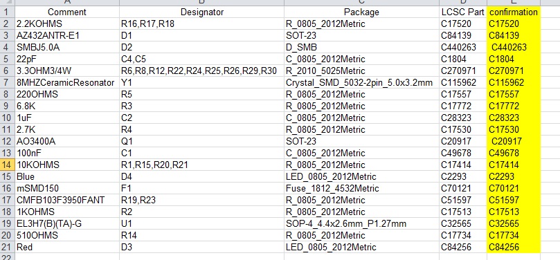
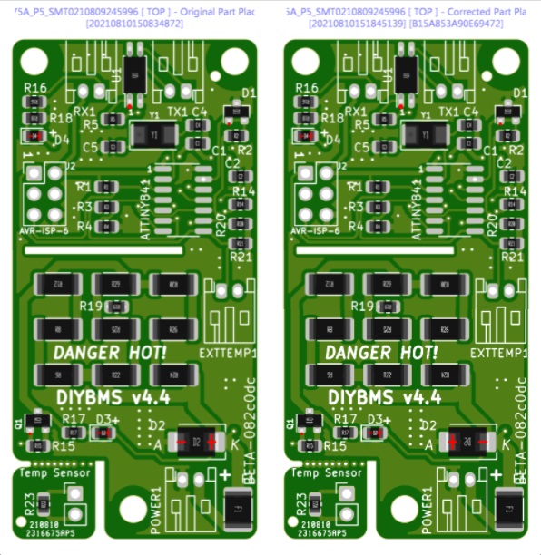
I think yes. I was confirming all the references used by jlcpcb and they are right with the BOM. I attach a image with the verification of the references and also a image of the placement of the components.Processing: bom.xls…
Processing: bom.bmp…