Good evening everyone,
after looking at the source code, I noticed the query on “counter < 8” (main.cpp). Could it be related to the fact that the package 8 is not sendet to mqtt broker?

You can try removing that condition entirely. I think it may have been added for debug purposes.

i dont know how difficult an update is for a working canbus
but many people requested this
does someone know when this updade will be released?
@stuart At minute 12:47 of your current monitoring launch video, do you have the rs485 +5v line at the controller connected? The m-usb hides it from the camera. Should it be connected to the current monitor? And then I suppose that the controller would be powered through it from the battery and no other power needed?
The current shunt is self powered from the battery.
However, you need to connect all 4 cables of the controller rs485 to the same pins on the current shunt.
Hi Stuart
Finally we have the 20 DiyShunts from the Spamnish Team.
Everything has gone very well, and although I have left my eyes a little, it was possible to weld all those small components.
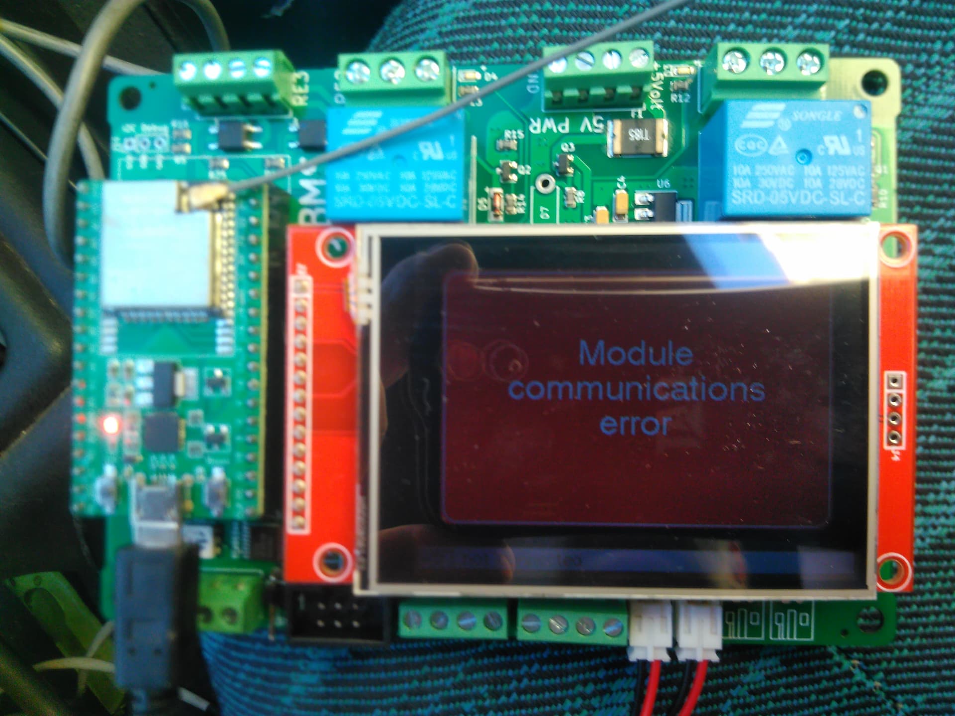
I have tried the 19 and they all go well, but there is a last one that does not work, I put a video with the sequence of lights in case you can tell us where you think the problem is
Autoedited to elimiminated the link to the video sorry
Looking at the programming, I think I can identify 8 flashes in the sequence, so the problem would be
//8 flashes 10101010101010100000000000001111
const static uint32_t err_CheckSumErr = 0xAAAA000F;
How could I deal with a solution?
@Chapulino
From the FAQ:
Sorry. Thank post edited
I’ve never seen that error, but it means that the INA chip has a corrupt configuration/memory. Possibly a bad chip?
Take a look at “MEMSTAT” register in the documentation.
I don’t think so, it is one of the same 20 that Texas Intrument sent me from the USA.
Maybe it was damaged by heat in the assembly or, although it is rare not impossible, it was defective, it only remains to change it I imagine but it is very lazy to order just one because of the high shipping costs.
Thanks Stuart
@stuart
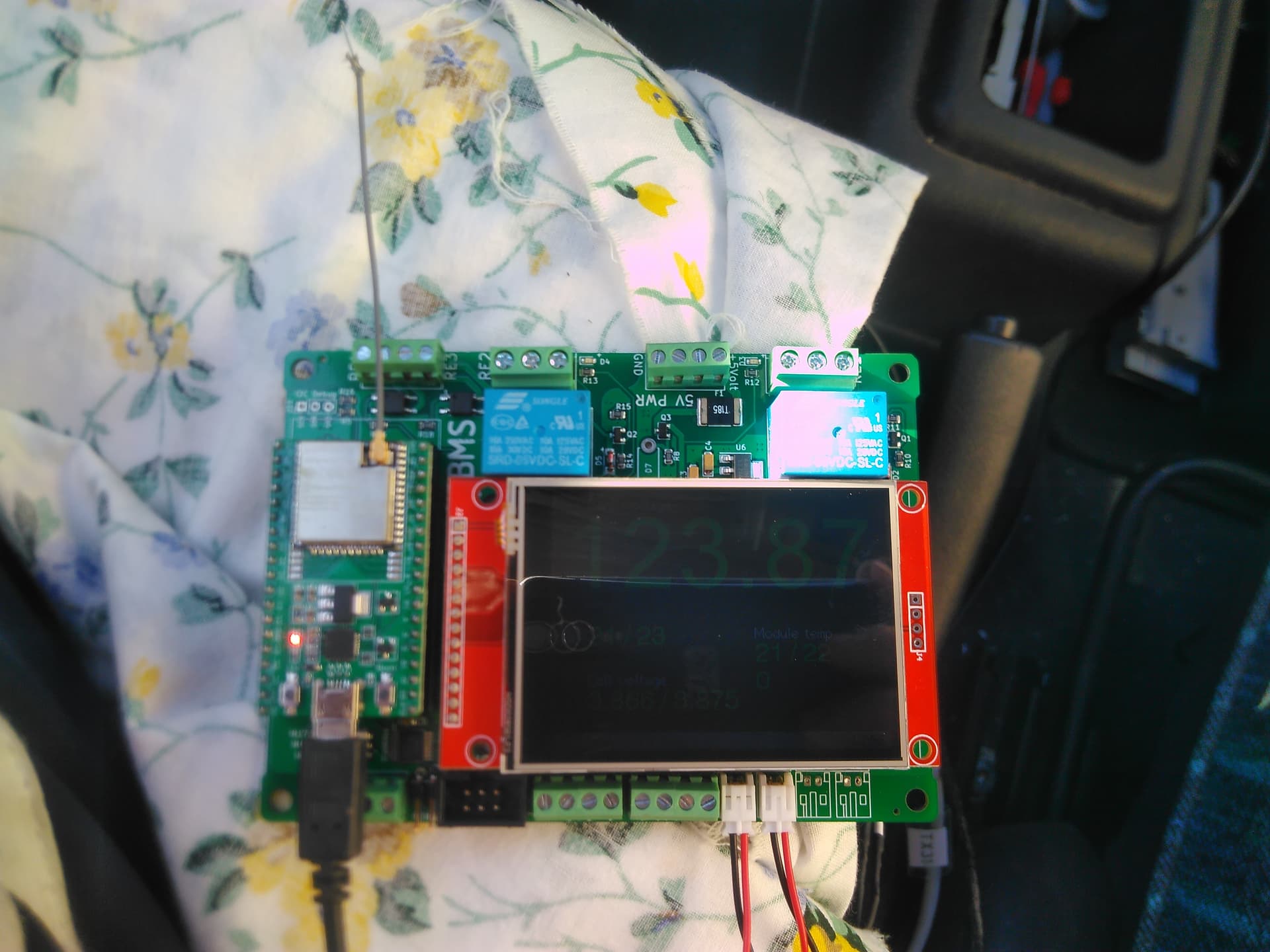
I am running the old controller with v4 modules. I see fluctuation on the voltage readings, see this video, is that normal ? You can see the readinf from the fluke meter which seems to be stable. As far as i can see all modules reacts the same, maybe it’s normal. I am measuring on Cell #15 with Fluke so it’s the one selected in the UI.

FYI: At the time of the video battery was beeing charged with 10A which is nothing compared to capacity of 160Ah and batery was around 60% SOC
I think diybms works in that way. The same occurs to me.
When did you build the V4 modules? There were reports of a bad batch/inaccurate tl432 chips, which are the main voltage reference.
my voltages also vary even when not charging but only a few mv.
how accurate is the module if you add 0.001v will it actually go up 0.001v?
My multimeter reads 0.025v too much right at the max error on the datasheet 3%.
No it’s not that accurate, from memory the module resolution is 0.004V, or 4mV.
i understand that is why it jumps ± 5mv when calibrating, if the reading goes up 5mv while you type you will be out by 4 or 5mv because it jumped to the next value.
@atanisoft , I’m in a bit of a hurry. Stuart tells me you might know someone who can build me some of these boards. If so, please DM me so we can discuss. Thanks a bunch.