Have not been able to test with relays…the board keeps rebooting randomly. So far i have tried 4 different powersources, on the controllerboard, but also via micro-usb on the controller itself, same result. Also tried uncoupling cell modules same thing, Maybe I can try a previous “code”? Or try/order a new esp controller?
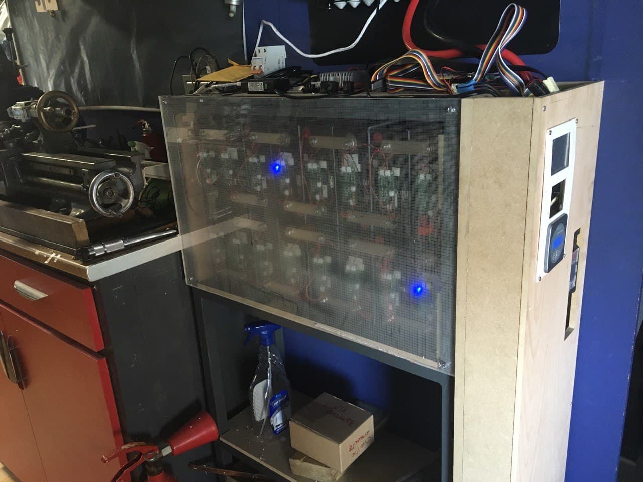
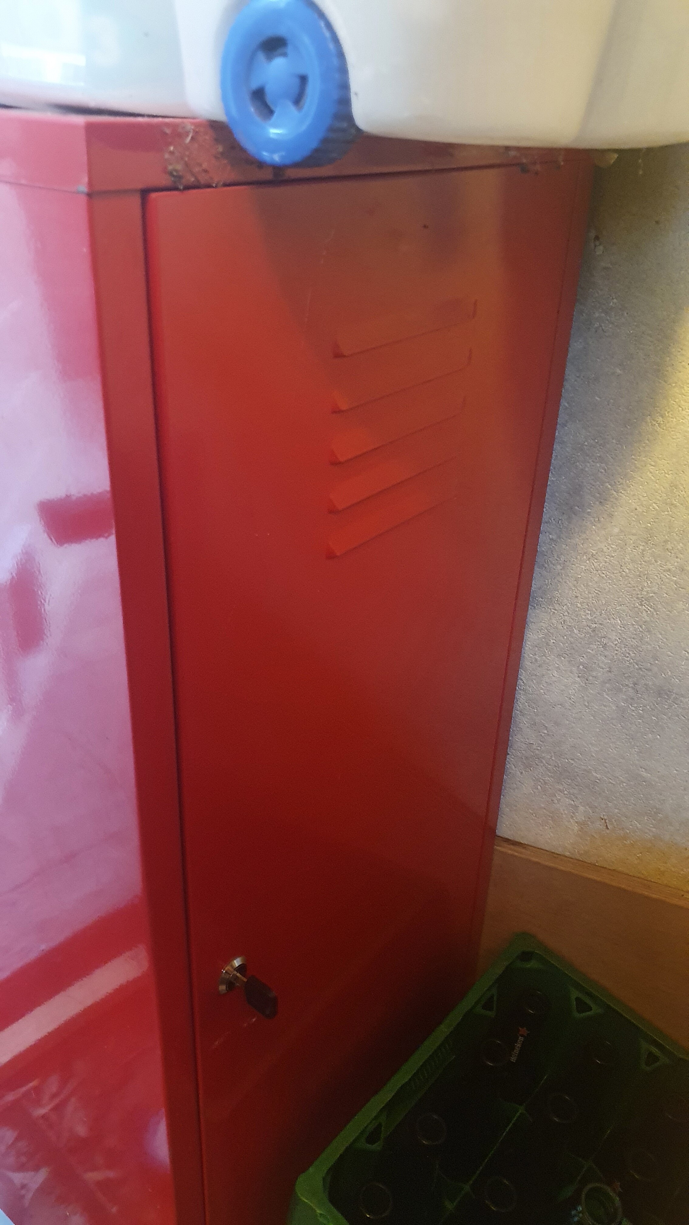
This weekend I am moving my leaf cells to 2 lockers, these will be housing everthing but maybe not the controllerboard depending on wifi performance.
the IC (ADM2483BRWZ) for the current monitor for handling RS-485 is out of stock at LCSC and all USA retailers. I’ve found a bunch in Europe that I’m about to order if need be.
AnalogDevices the manufacture of the IC show that the ADM2483BRWZ can be replaced by ADM2761EBRWZ. which is in stock at lots of retailers…
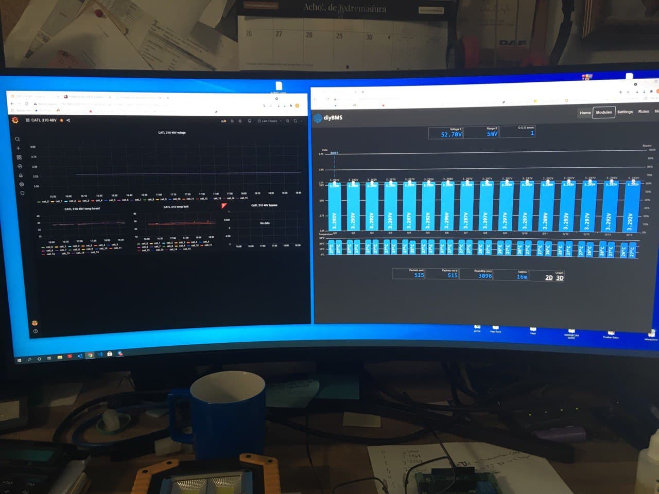
Because you can view the “uptime” on the homepage, but also i see logs in my wifi; connects, disconnects and authentications are logged cisco meraki hardware and online suite
my bad the green leds is correct. I’m running 4,21,modules and what I see is all module will flash then the comtroller. The wemos will then flash blue. If you can see the web interface then the break down is between the main controller and the wemos? can anyone verify this is correct?
have you tried just hooking up 1 module and seeing if it is viewable on the interface?
the code I loaded was pre 2021 using platform io. haven’t been able to figure out how to use the new method of uplaoading so I’m dead in the water programming my last cell modules and controllers.
something has had to of changed for everything to be working one day then not the next. any issue i have had came down to bad soldering. some of which without a magnifying glass I would not have found.
hopefully someone with more knowledge then me will chime in. electronics and coding are not my bag.
Hey guys, was just wondering if there’s another place to buy the diyBMS aside from JLCPCB? I’ve already tried several times over 2 months and there’s always some (hard to solder) SMD component out of stock. Thanks
I replaced the controller pcb and the issue with non switching relays with latest fw is solved… very curious, because with release from may 2021 ist worked but not with later ones…
there is still a “time out issue” - module 43 out of 70 is giving time out flashing signals
there are still two modules with very low count on packets received…
I found the current module upload instructions using avrdude both limited and a little confusing. What I had to do to get it working for me was to install and run a program called Zadig (v2.5) before I could get avrdude to work for me, and even then I had some modules require the ‘-B8’ command line command to be changed to ‘-B16’ (as Stuarts suggested) to get some modules to take the code. Finally, I had to, at times, then unplug and re-plug in the USB of the USBASP programmer into my computer to get a new module to upload the code. Ultimately, those steps got it to work for me.
I have used a digital microscope to check all my solder connections, both those performed by me (attiny841 and the D1 ic) and those from JLPCB and still needed to make 11 modules to get 8 that appeared to function correctly. No idea why the other 3 arfe more … variable in their performance.
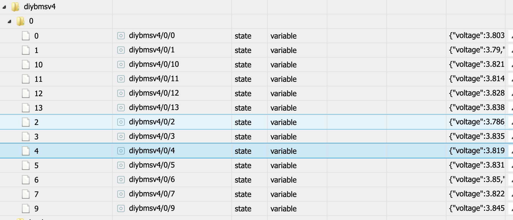
Hi, today I updated my old esp8266 controller to the new esp32 controller board with display. I use mqtt, but I don’t get the cell values of cell #8. All other cells update. On the bms webpage I can see the cell 8 voltage. Do you have an idea, what I can do?
 cisco meraki hardware and online suite