Yes you can, but the controller with show a warning message
It already is! The module measures the individual cell voltage, so less than 4.5V per module
Thanks for the quick reply… I want to monitor the whole 48v pack with a single module…so 40-60v each module.
Thanks again.
@stuart
I have my packs setup as a 1s12p 48v pack. (12 - 14s2p on a common buss)
At this point I wouldn’t need balancing but pack voltage and temp monitoring would be great.
I really like this product and I’m using it on my Lifepo4 bank…
The way I built the other packs doesn’t make it practical.
I hope this is clear… Perhaps there is another product that I could use that I don’t know about.
Thanks again!
Michael
Does anyone have a recommendation for a 60v 200amp isolating solenoid to use with the diyBMS?
I’m not sure what to look for… or even what to search for on this forum.
Thank you for any input!
Michael
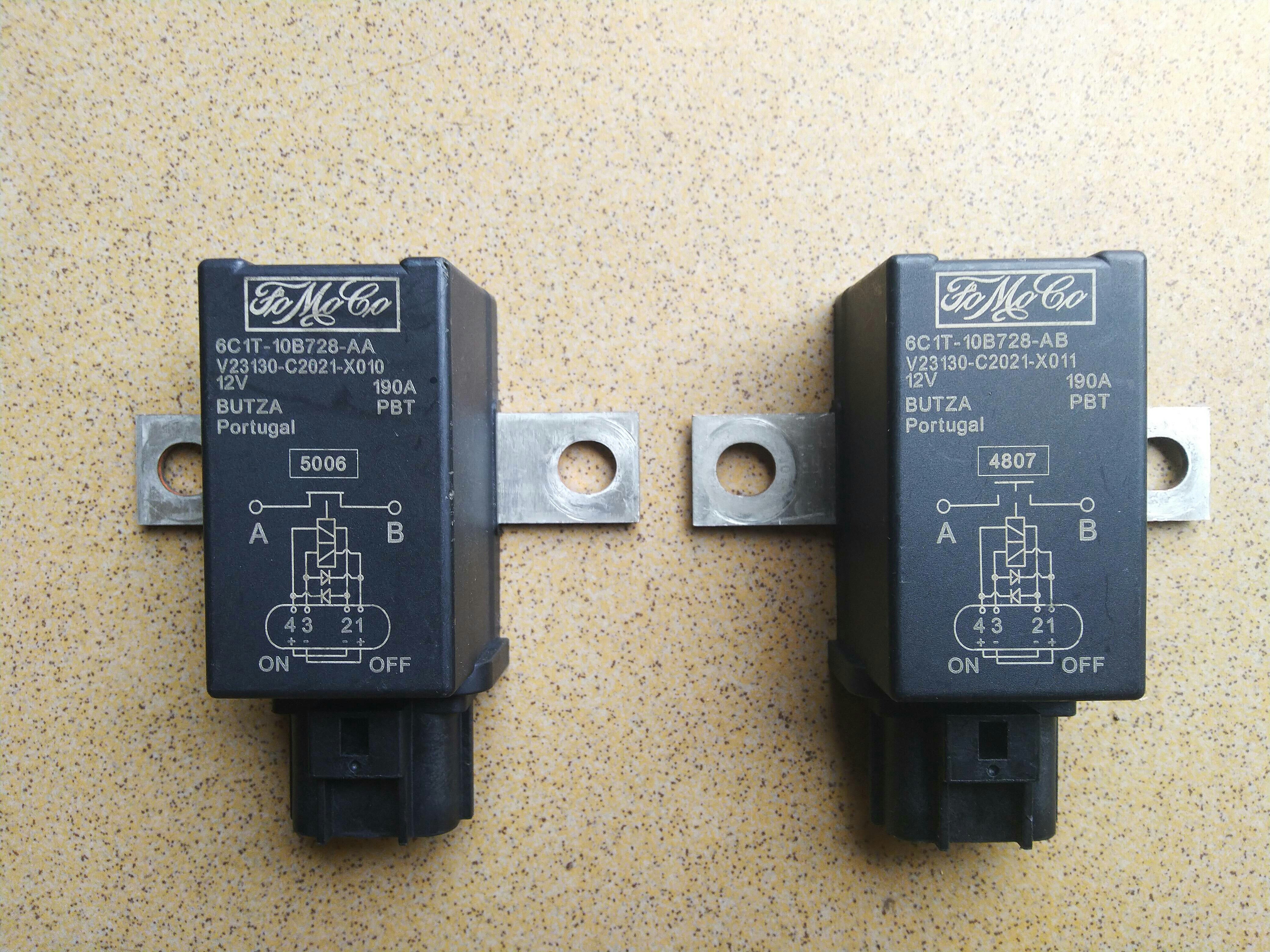
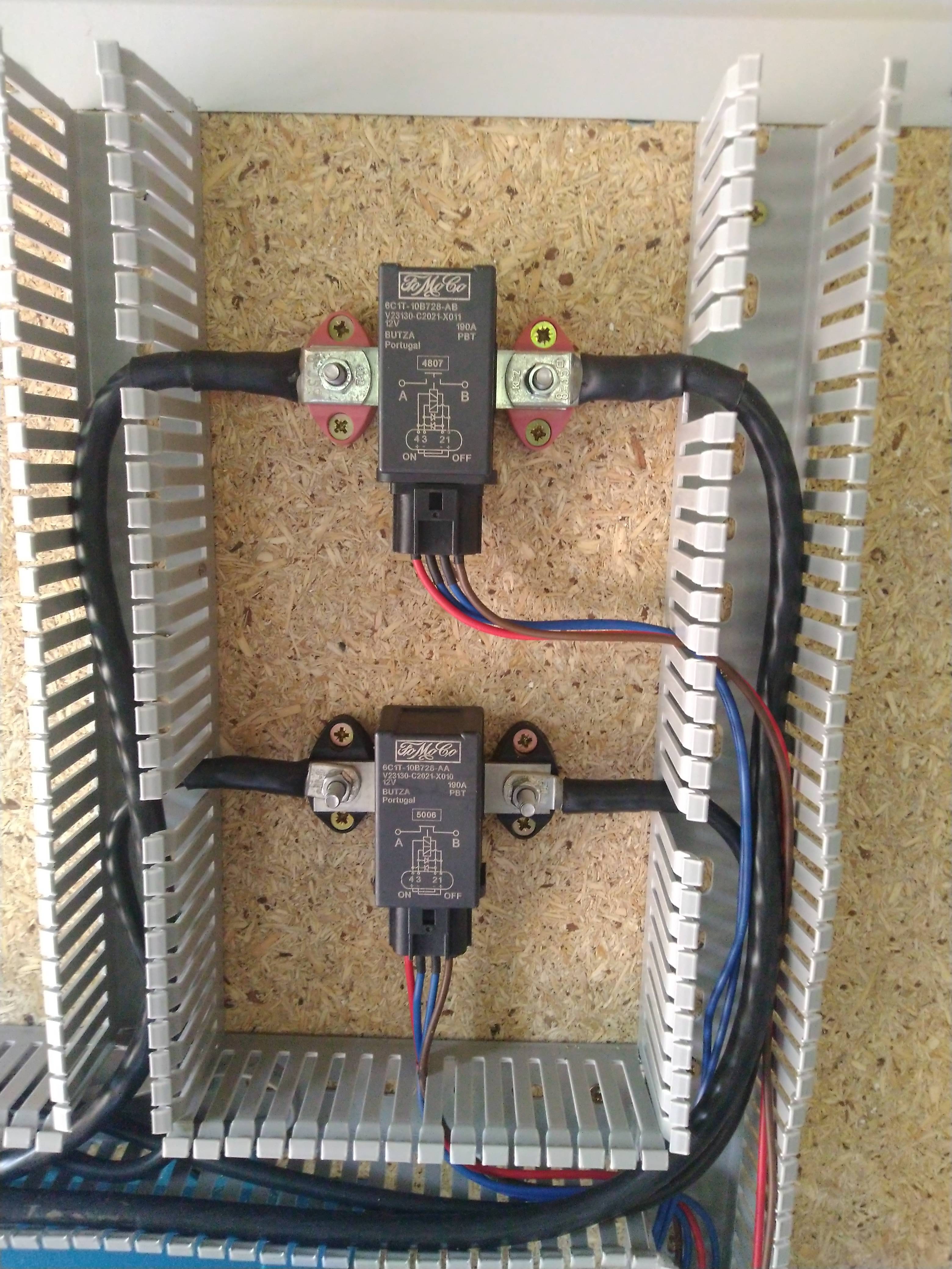
Look up for a EV200AAANA its quiet cheap on Aliexpress.
As here: Recommended products to disconnect battery using a relay - #9 by wmichale
Thanks for the reply… I ordered one this morning!
Thanks for the reply! Looks like this is the way to go!
INFLUXDB Integration on ESP32 with multiple strings.
Hi.
On the build from 11.May 2021 and from the last one (July 2021) there is an issue I think.
Only the first batterybank shows correct values, all others show the exact same voltages as the first bank.
In this example I take all values from cell 12 in each bank and they are exactly 3.876Volts each, which in the diyBMS Gui isn’t.:
SELECT last(“v”) FROM “cells” WHERE cell =~ /_12/ GROUP BY “cell”
name: cells
tags: cell=0_12
time last
1625916044636554602 3.876
name: cells
tags: cell=1_12
time last
1625916044636554602 3.876
name: cells
tags: cell=2_12
time last
1625916044636554602 3.876
name: cells
tags: cell=3_12
time last
1625916044636554602 3.876
name: cells
tags: cell=4_12
time last
1625916044636554602 3.876
And here from last build:
SELECT last(“v”) FROM “cells” WHERE cell =~ /_12/ GROUP BY “cell”
name: cells
tags: cell=0_12
time last
1625916318692299056 3.987
name: cells
tags: cell=1_12
time last
1625916318692299056 3.987
name: cells
tags: cell=2_12
time last
1625916318692299056 3.987
Is this using the influx API call. Or via Mqtt?
Its the influx thing, Integration/Influx.
mqtt is disabled on the controller
Is someone flashing the esp32 controller on linux, and can explain me how?
The suggested nodemcu-flasher does not work on linux as it uses obsolete dependencies. And I can’t find the correct parameters for esptool.
$ esptool --chip esp32 --port /dev/ttyUSB0 --baud 115200 --before default_reset --after hard_reset write_flash -z --flash_mode dout --flash_freq 40m --flash_size detect 0x1000 esp32-controller-firmware-complete.bin
esptool.py v2.8
Serial port /dev/ttyUSB0
Connecting........__
Chip is ESP32D0WDQ6 (revision 1)
Features: WiFi, BT, Dual Core, 240MHz, VRef calibration in efuse, Coding Scheme None
Crystal is 40MHz
MAC: 08:3a:f2:a9:e4:70
Enabling default SPI flash mode...
Configuring flash size...
Auto-detected Flash size: 4MB

A fatal error occurred: File esp32-controller-firmware-complete.bin (length 4194304) at offset 4096 will not fit in 4194304 bytes of flash. Use --flash-size argument, or change flashing address.
PS. Reading again the output… could be a full flash binary?
Yes it is, you need to program it from address zero
Ok, please raise an issue on github for me [GitHub - stuartpittaway/diyBMSv4ESP32: diyBMS v4 code for the ESP32 and new controller hardware]
So 0x0? Yes, already flashed it. How stupid I am.
Perhaps that cmdline could be added to the readme for a lightning fast flash on linux.
PS: Adding the line that worked for me:
esptool --chip esp32 --port /dev/ttyUSB0 --baud 115200 --before default_reset --after hard_reset write_flash -z --flash_mode dout 0x0 esp32-controller-firmware-complete.bin
@stuart , do I have to do any modification to the new controller board (JP5) if I were to use 5v through the screw terminal?
Long thread. I’ve tried my best to parse it to see particular comments related to my issue(s) but it’s almost futile at this time.
The basic issue, running 4.21 boards with the (V4?) esp8266 controller, and I am having a significant issue trying to have them run consistently. My boards were ordered a fair while ago but I have only just gotten around to putting them together. They were largely made by JLPCB, I had to solder on the attiny’s and the voltage regulator/reference chips.
I’m running an 8s(1p) LiFePO4 battery bank and I am having quite varied voltage readings from the boards. In the range of 0.25-0.4 volts even just over the course of 24 hours. I am not yet running any loads on the battery bank just trying to get the BMS going first.
Additionally, I am now getting inconsistent module communications, to the point where I have removed all the boards from the battery bank to look at some troubleshooting because the modules were not showing up on the web interface.
On the surface it appeared all was working as expected, all of the modules were displaying the flickering blue LED (indicating they were getting power from the cells?) and they were also flickering the green (?) LED, in sequential order, seemingly indicating that the communication loop was working as intended but still no dice on the web interface. I have previously had the web interface working fine. Nothing seems to have changed other than the initial issue of inconsistent modules.
Is there any other way to ‘confirm’ things are working as intended on a basic level? Is my assumption of the LED flickerings accurate?
I am running * module_fw_V421_attiny841_421_eF4_hD6_l62.hex on the modules and * diybms_controller_firmware_espressif8266_esp8266_d1mini.bin on the controller.
I do have very poor internet where I live, like really bad and so my house wifi is possibly a factor? Additionally, perhaps my soldering skills can explain the inconsistencies? Is it likely multiple issues I am facing or are the inconsistent module cell voltage readings related to the web interface issues?
Thanks for any insight or advice.
check everything you had to solder including the header pins. If the blue LEDs are sequentially lighting then it sounds like they are communicating with the controller.
for the voltage float issue: are these new batteries? were they balanced before connecting together? are they matched cells as in did you capacity test them?
You mean sequential green LEDs right? The blue LEDs light up as soon as a single module connects to any cell … the (I think) green LEDs light up sequentially once the loop is complete.
I’ll check all soldered connections but the sequential greens seem to suggest it’s connected correctly?
Secondly, they are used cells. I have top balanced them. I have not performed a capacity test. The floating voltage issue appears to me too be an issue unrelated to the batteries though, as with voltage checks with a multimeter shows no change in the cell voltages yet the Diybms would like me to believe the cells have varied by 0.25 to 0.5 volts in some cases. That does not seem related to the cells being used right?