ok, but you can set max. pack voltage and max. individual cell voltage. if cell voltage exceeds 3.6V, my bms turns off the charger… in case you have set it for 3.6V max cell voltage… in the mean time bms can try to get high cells down and then bms kicks in again with allowing charger to charge…
Yes you can set it and that’s how i already set it but you need to be aware of that diyBMS have a turn around time of 3s in the case of 16s configuration which means it takes 3s before the next reading is made and in that 3s the voltage can get quite high when the charger pushes 50-80A to the battery. Ofcourse diyBMS does what it should when it sees the voltage high it turns off the charger then the bypass brings the voltage down and then the cycle starts again with the charger pushing max amps out. I look forward to when(if he has time) stuart get’s time to look at can interface integration for my Victron and in that way there is an more inteligent way to talk to the charger and tell it to slow down for example so the BMS can keep up. Another thing which one needs to be aware of (maybe it’s my case) is that when using the relays to turn on/off the charger then during a charge cycle the relay will switch on/off mabe 30 times if not more. A realy has a short timespan so it will eventually fail and stay closed and then the cells can get damaged. Again this might just be my case because i have not top balanced (i take all the beating here ) and the BMS must try to balance and this happend often.
ok, i have 3 victrons pushing 105A in my batteries. With a usable capacity of 35kWh “nothing” happens within 3 seconds…
When you get to max. package voltage, the victrons lower current due to constant voltage mechanism… it is just in your case a bigger problem, because cell voltage vary dramatically. I don’t have any such problem and it doesn’t apply to the crowd
Hey i think that’s great to hear at least, i am trying do dismantle the pack and put them all in parallel then try again and see. I have one more spare cell, not sure whether i should wait with that one or just swap it right away hmmm…
in order to balance my pack at the very beginning, i set victrons to 57.6V at 100W charging power and set balance voltage to 3.6V. Then, diybms does everything on it’s own… just wait!
100W covers own consumption of victrons and charging for balancing.
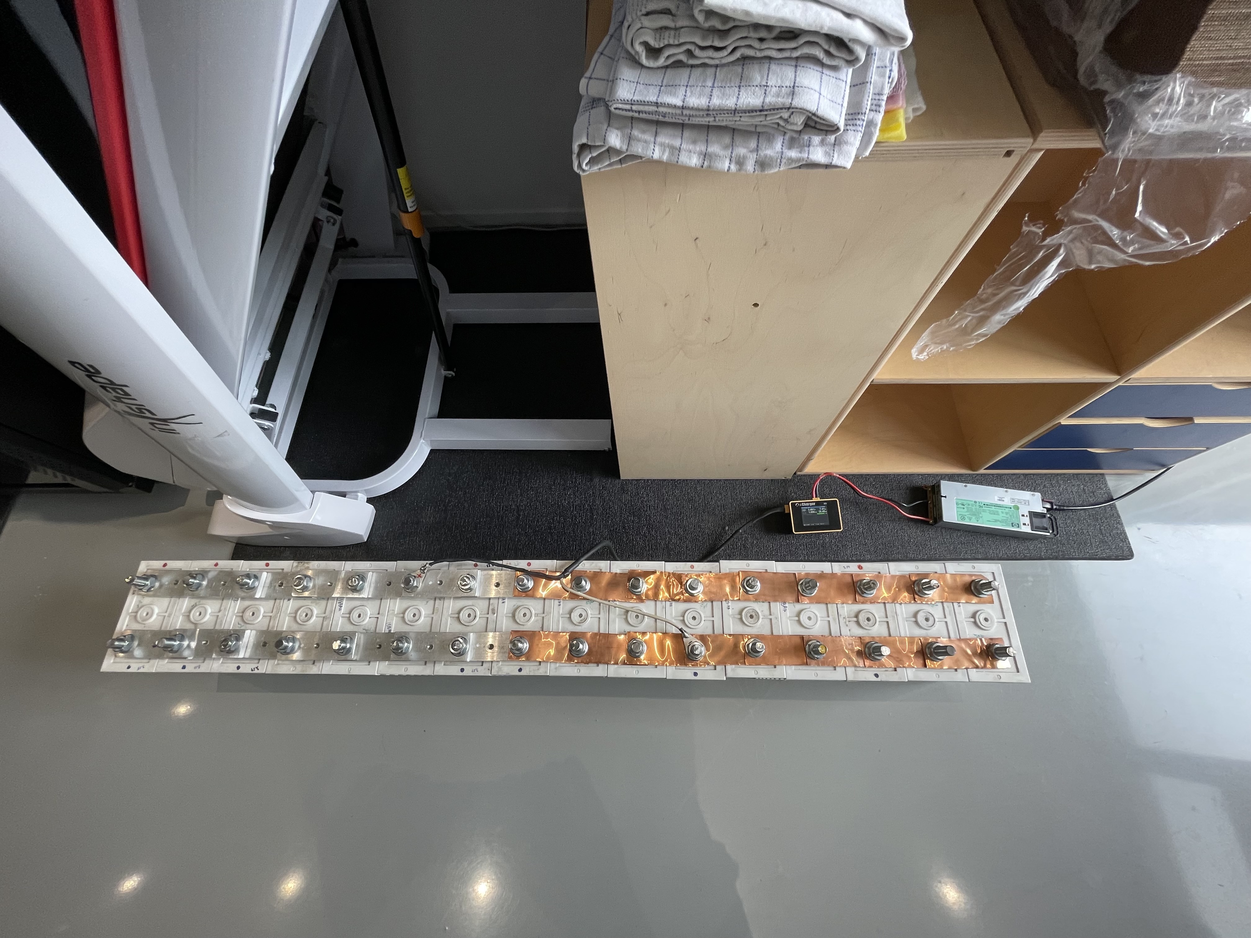
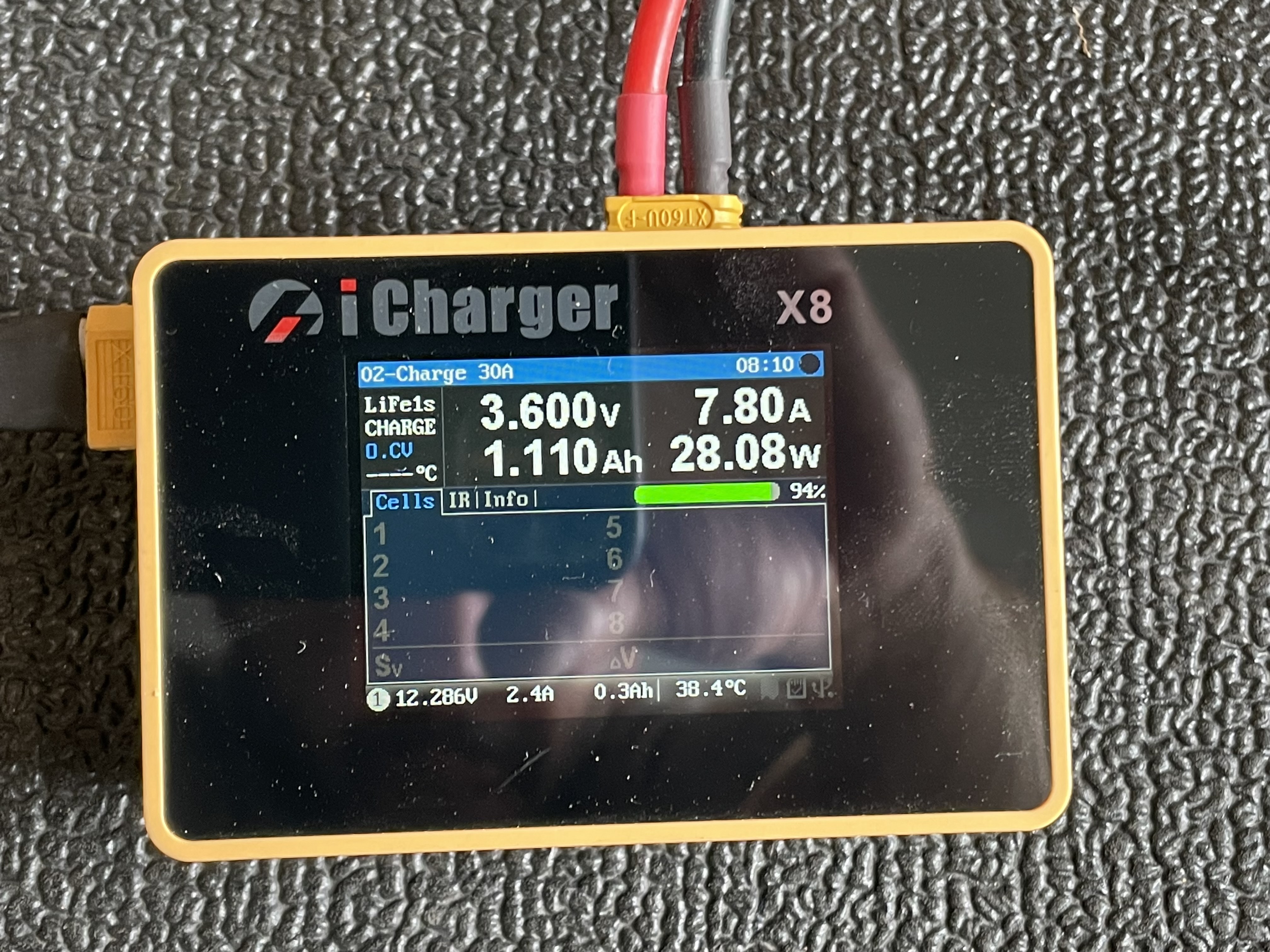
Now i have dismantled the battery pack, it din’t take that much time but i ran out of busbars so i have to improvise some out of some copper sheets but i started already with the 8 cells connected in parallel and set the icharger to charge them. How long did it take for you with 100W to reach absorption ? So you set 3.6v as bypass ? In VEConfig when you choose LiFePo4 it set’s the Absorption to 56,8v meaning 3,55v. I had mine set to 56,2v and 3,5V bypass.
When you have a close look at the discharge-curve you see that there es more or less no capacity left between 3.4 and 3.6V which is a good basis for perfect balancing.
I would keep 3.55V for absorption and set bypass at 3.55. Power at 100W. This won’t take long in case your cells are above 3.35V. Below 3.35V there is a long way to go until voltage goes up.
This only applies when you don’t dismantle packs.
When you use your icharger and have all cells in parrallel than set icharger to lifepo and charge it up to 3.6V with full power. the icharger does the rest.
Sure i follow what you are saying and that’s what i did, now waiting. In all rush i forgot to note down which cell caused issues before so i can keep an eye on it when i put it together again
After charging your cells leave them connected in parallel for a day to have the charge balance evenly over the cells and do not charge the cells with the charger connected near the center. Connect positive on the far left and negative on the far right, that way you also even out the resistance of the bussbars.
I charged everything together, different places, i did it twice in the middle of the pack then at the ends twice and i measured the voltage in the ends and the voltage drop was very little. I gathered the pack again and put it back, now waiting for next charge cycle when sun has enough power and will see how it goes this time.
Hi Stuart,
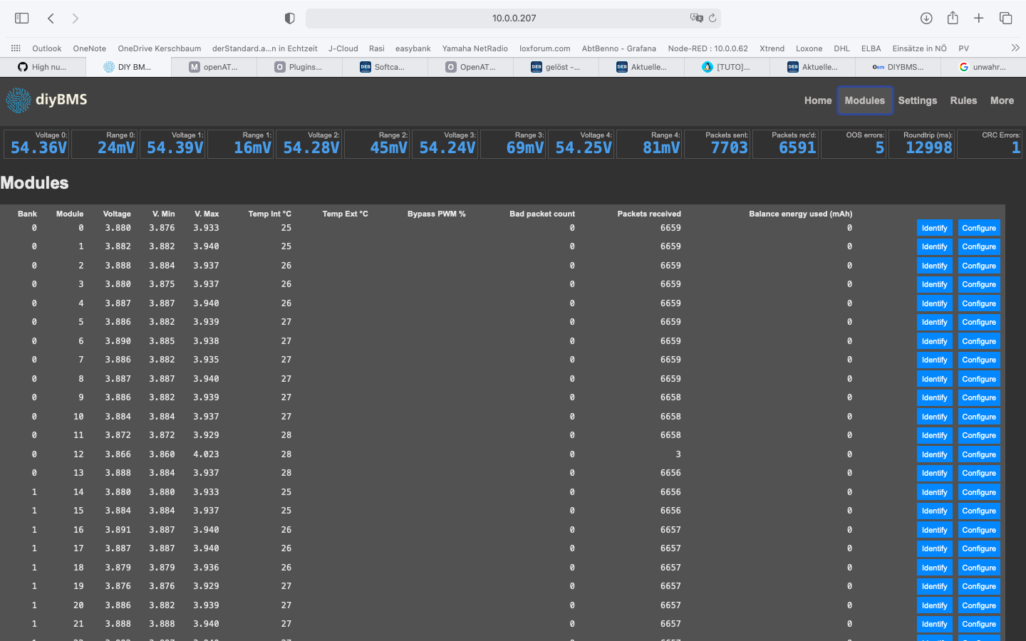
i did an update on version 07/06 and having two issues:
still no relays switching on
wrong voltage readings just 15 seconds after calibration on 3 modules. switched them but issues on the same position…
Module 0/13 and 2/5 are giving me issues…
Maybe I should split up to 2 controllers. I’m going to try 3 banks in total and see how it behaves…
But curious, that even when I swap module 12 with module 11 (first one is 0) then problem remains with module 12… it is unlikely that this is a coincidence…
When I load firmware from may 2021 and go to settings and set relay 1 and 2 to always on, they switch immediately when I press save… not with later versions…
I need them always on because i allow charge and discharge for victron. they are switched off, when relay triggers due to rules…
can you check that in your environment whether to get relays to a steady on…?
Just one more finding on that topic which we talked about. there is some kind of communication issue because “packets received” count for module 1/12 is way too low…
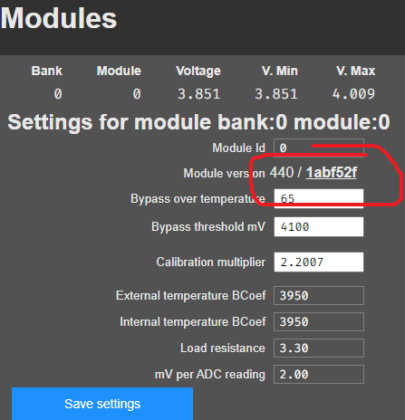
fy the way, can I run my system with different fw-versions on modules and if not, how can i find out which fw-version is loaded… just in case i have to swap a module with a new one…
On the module 1/12 issue - I think this one has a faulty JST cable which is frequently resetting the module - especially as the problem doesn’t move when you change the module.
Just another thought - are you running in the default “english” language setting - a long time ago reports of the rules not working properly when spanish language was used, but that was before the recent language changes.
@stuart
I have a bank of 12 - 14s lipo’s. It would be great to use one controller and 12 modules to monitor the temp and SOC.
What would it take to make the v4.4 module 40-60v capable?
Is it even possible?
 ) and the BMS must try to balance and this happend often.