If you can, capture the console output for one of these restarts as it may be a crash due to memory issue. I haven’t seen the esp32 crash in my tests, similar to yours where it is sitting on my desk with a 7s2p 18650 (Jehu PCB) with modules connected to the required places.
1 Like
I’ve not seen any randomly generated reboots for some time on my test rigs, longest is up 33days+
Check you have at least a 2amp 5v power supply.
I’ve seen strange behaviour without that, particularly if you have weak WiFi signal.
1 Like
I am not sure how to capture that console output, could you explain how I would do that?
I did find i was using a weak powersupply (only0.7a)…
Now changed to a 2a. The wifi signal was arounf 3/4 with controller in house, now that it is in the shed it dropped to 1/2 signalstrength. Fingers crossed.
Still can’t change time though…
Connect a USB cable to a computer and capture the serial output that is generated. It should default to 115200 8N1 for the serial settings.
If it was a 5V supply that may be OK for most things but it is right on the edge for too small for the ESP32 WiFi (600mA 3v3 minimum during TX). Which specific ESP32 board are you using? Is it one of the Espressif branded (not just the SoC itself)? On most newer ESP32 modules it is on the bottom side. I ask since some knock off boards use only a 500mA 3v3 LDO (bare minimum per datasheet) which will have issues under some circumstances (ie: low WiFi signal). The Espressif boards typically have a 1A 3v3 LDO.
1 Like
Ok, perhaps a bug, is the time correct but hour wrong? Daylight saving etc.
1 Like

This is the one I got on the board, wifi signal seems to be ok from inside the shed at the end of the garden to acces point still 50%.
Uptime of 12 hours sofar
Not to worried about this 
Would it be quite simple to modify the v4.21 cell monitors and controller board to use the kind of screw down terminal blocks (that you have used on the new controller board) for rx and tx? I think it would be easier to get a bit of twisted pair from an old length of ethernet cable and screw it into the rx and tx connectors than to try and solder up longer cables using the jst pre terminated wires (with the red and black leads) that you have to manually twist and join. I know that there are some pretty small ones but I don’t know if the PCB would have to be modified for them to fit?
Not simple, no. The pin spacing is the issue. The boards use JST-ZH connectors, which are 1.5mm spacing. Those terminal strips have a pin spacing of 2.54mm.
I don’t think they make terminal strips with a pitch that small.
You could edit the PCB layout to change the through-hole spacing and then use that when ordering through JLC or PCBWay. You’d have to make sure the new through holes and pads connect to the circuit.
i bought myself a pliers with a bag of JST connectors with contacts, total cost 18 Euro on Aliexpress. Good enough to make my own cables custom length.
Not quite, they are PH style with 2.0mm spacing
Hi all,
I’d like to give a warning to all of you using diyBMS like i am, it’s a great project and i love it but you need to understand it’s shortcomings.
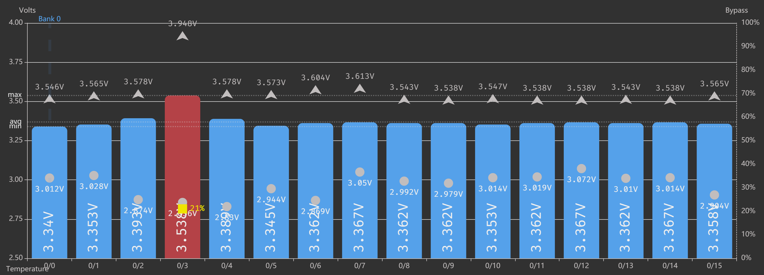
I have a 16pcs 160Ah LiFePo4 and the batteries are all in series to create a 48v battery bank, because i didn’t do a top balancing before i connected all batteries together like i should diyBMS struggles to balance at the same time the charger pushes 50 or more Amps to the pack, because of the long turn around time e.g 3s in my case cells can get dangerously high in voltage BEFORE the BMS turns things off. Because diyBMS can only tell my charger turn off or turn on and cannot adjust charge current one need to be careful not to destroy the cells. I had one cell get momentarily to 3,9V which is way to high for a LiFePo4. My rule is set at 3,6V but again because of the turn around time the voltage can still rise in those 3s above set rule.

/donnib
Why didn’t you do this ?
that cell that shot up to 3.9v is very low capacity compared to the other cells, you should consider replacing it. the range between the highest and lowest recorded cell voltage for that cell is greater than all the other cells. which means it discharges faster and also charges faster than the rest.
To be honest, I forgot  but I guess this problem can still happen even in the case of one cell aging. I might have to open the pack and do it since I am not sure I can get far like this.
Hard to say whether the cell is aging (it should not since they are not used much) or its because of the missing top balancing. I see many cells down to 2,9v so this one is not the only one but certainly wins at Max
I sat down to investigate the max and min voltage of all cells so here is a histogram of max voltage from last 30 days :
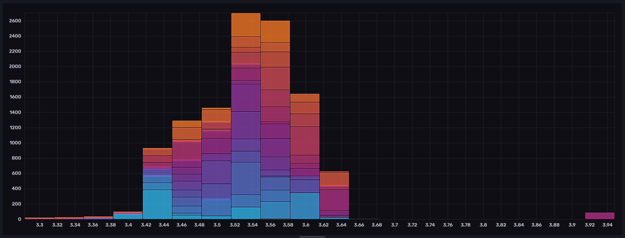
As you can see something stands out on the right, looking into that :
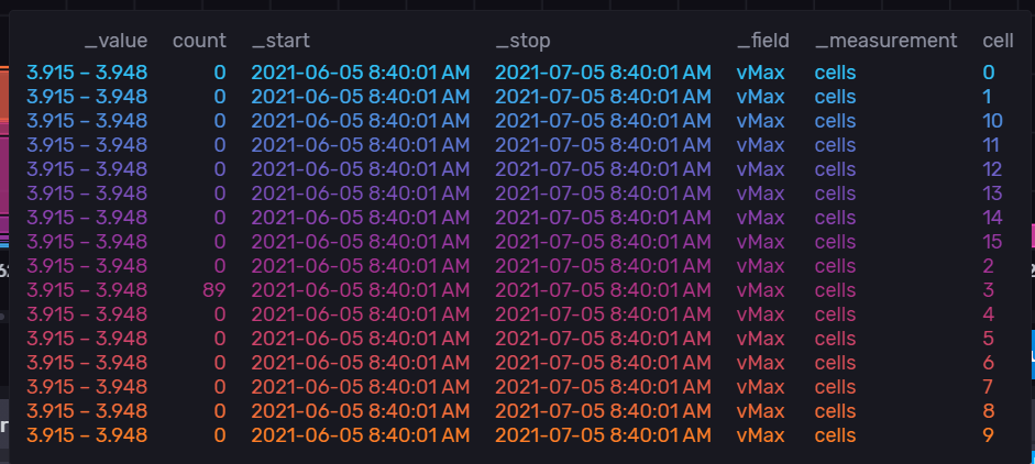
it’s clear, that this (cell 3) is the only cell reaching this high from all the cells.
Looking at the min values in the same timeframe it’s not a clear picture anymore :
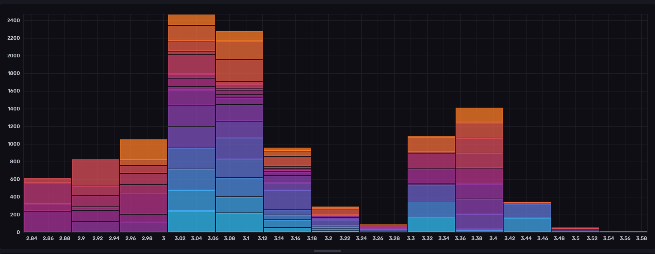
the lowest values in details :
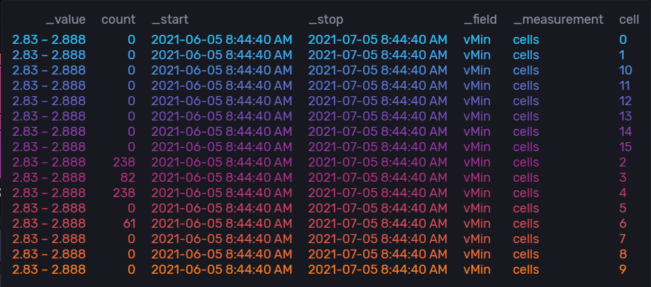
as you can see more cell go down to the lowest levels.
I am not sure i can conclude this is a aged cell or something else.
hi,
this is not an issue with diybms in special. you will see this issue with every bms. You won’t find any which can burn 50 amp!!! Do a thorough top balancing!
You can set max charge voltage to e.g. 56V and start balancing at 3.5V. By that, charger will reduce current when getting near 56V and bms has a chance to burn off excessive voltage of individual cells…
No one is saying the BMS is suppose to balance 50A ! I understand the shortcomings such as only one 1A balancing current, the issue here is that when charger pumps 50A it takes in worst case 3s (in my 16s case, if you have more cells then this number is higher) before BMS reacts to the high cell voltage, one needs to be aware of that.