Hi, I was looking for the IC ADM2483BRWZ and found one with the model name as ADM2483BRWZ-REEL. Is there any difference in the ADM2483BRWZ and ADM2483BRWZ-REEL models?
Its the same thing, just one is on a REEL ![]()
Octopart is your friend in this case…
https://octopart.com/search?q=AQY212GSZ¤cy=USD&specs=0
1 Like
I’ve not started looking at that at the moment. Do you know of a simple way I can get a Victron test lab setup without buying Victron kit?
Does anyone have any broken Victron kit that still communicates with CANBUS ?
Thank you Stuart!
I have mistakenly ordered the lcsc part C49678 to be used for C6 and C14 of the current shunt. The difference is this one have the voltage rated at 50v. Will this be OK or do I have to order one with 100v?
I can send you a cerbo GX for testing.
Please send me a PM with your post address.
1 Like
What voltage are you planning to monitor? Is it less than 50V?
My system is 24v. The shunt is to monitor the battery in and out.
At 24v it would be fine to use 50V caps - no good if you were running 48V though.
Thank you! I’ll let you know if anything went wrong.
is there anyway to stop the relay clicking off then on when the device reboots, i have a shunt trip on the old controller and when resetting the controller the relay will stay on when its set as on as default.
on the new controller it seems to click off and then back on when it reboots, this is no good for my use as i rely on the relay to hold my shunt trip breakers on and if the controller was to fail or over volt error then it will release the relay to turn the battery off for the house.
i dont want it on the NC contacts and then to turn relay on as if the controller was in a error state or not working then it would not activate to turn off the shunt.
Not that I know of, the output to the relay will reset when the esp reboots.
There is no essential difference between rebooting and failing. If you want it (anything for that matter, not necessarily DIYBMS) to fail into a desired state - normally “safe”, then you have to accept that it will go into that state while the electronics & software are not in complete control. There’s no way around that.
It’s more to do with the mqqt server not outputting say when I do a homeassistant version upgrade the mqqt server is put on hold whilst it upgrades and after about 3-5minutes of the diybms not seeing the mqtt server it just stops working even if the homeassistant has fully loaded up again. Only way to sort it is to reboot the diybms and if that means it trips my breakers whilst rebooting then no good  guess I’ll have to just use normally closed and then make it turn on relay in a fault scenario to turn off my battery bank.
Rather than rebooting the controller, how about disable/enable the MQTT setting?
Hi
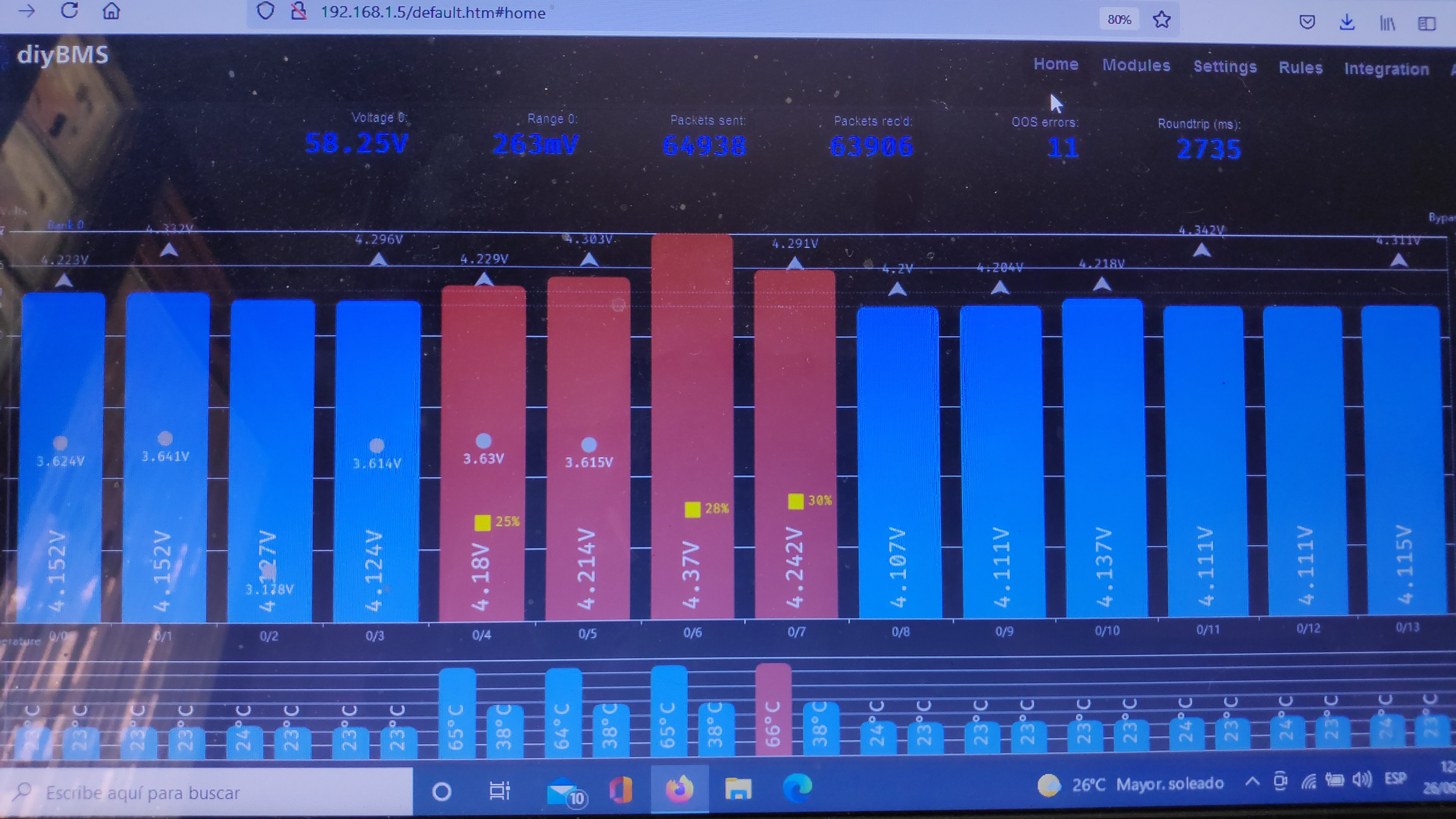
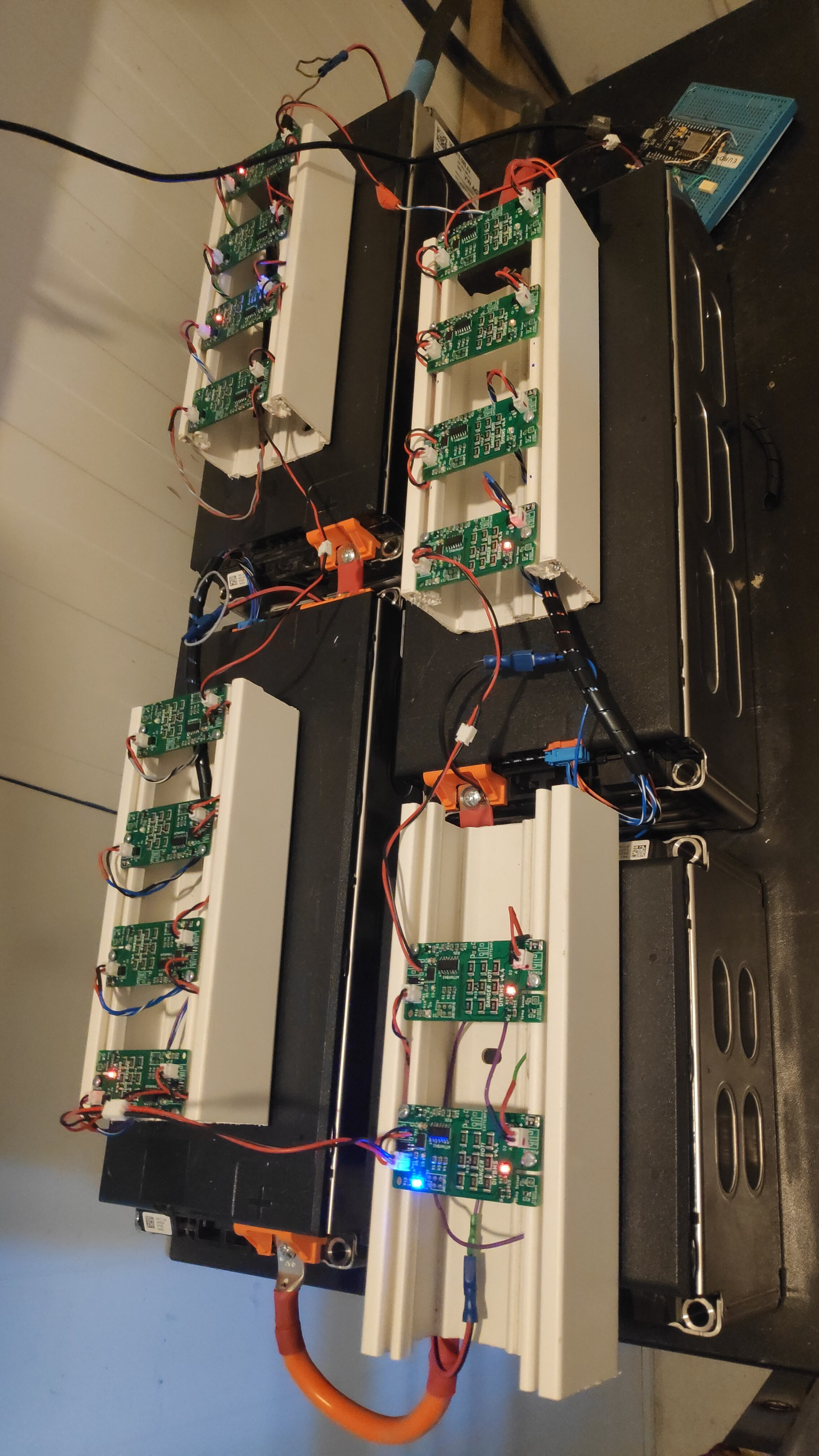
Finally I mounted diybms with EV cells. “Comon wire” efect is visible because use of balancing conector.
What relation between bypass voltage and mppt voltage charger should be recomended?
Which EV cells are you using? Also what rail system are you using to mount the modules?
What I’ve seen suggested everywhere is set the MPTT to 0.1v lower than bypass in diyBMS. This way the charger should stop charging before the cells go into balance mode so they will only go into bypass when they go out of balance.
Thanks. I’ll program my system for that, expect to minimize cell balance.
The cells are samsung SDI for VW e-golf. 5.6kwh
Rails are unex u23x trunking cable tray