Is the controller supposed to move off of stabilizing with the tx and rx connected together?
Does the shop have controller also? I dont see it listed
Latest ESP32 Firmware [Release-2021-06-16-12-11] has the following error
All 4 relays (Solid State and normal) on NEW ESP32 Controller not working / switching on.
Reflashed with this version and it works
Version: [3e1776b1a0d8941398d2eab576b4e2af8ec25a6e]
Compiled: 2021-05-11T11:41:15.777Z
Looks like a bug, will have a fix out ASAP
1 Like
Not at the moment - can’t get the parts!
No, its waiting for modules to reply - which they won’t.
What are you trying to achieve?
This issue is now resolved.
1 Like
I am waiting on parts for the v4.4 modules, so while I’m waiting, I built the controller. I connected the controller’s rx1 directly to tx1 half expecting to see the ‘Stabilizing’ screen change, but it didn’t.
Then I connected up my v4.20 modules to the new controller, less-than-half expecting them to change the new controller’s state; it didn’t.
After talking with you about it, I am relatively sure that once I build the new modules, they will all work together just fine.
Then I saw your post :
And thought I should clarify that comment in my mind.
Once I get past that and have modules working with the new controller, I will need some assistance with a code mod to remove the ‘blip’ that the dump load signal has. I am going with a relay-controlled dump load instead of the on-board resistor bank.
Ah, I see.
The stabilizing screen means that the controller is waiting for all modules to return a reply and a valid voltage reading - that state will remain until modules are connected.
The web interface should still be functional at that point though.
The V4.2 modules should work - as long as they have recent firmware installed, you can use the new controller to program them (disconnect module from battery first!)
Well first impression are not good…
At start, all cells around 4.05V and bypass fixed hight to 4.20V:
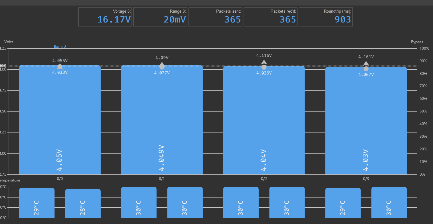
Then down bypass to 4.05 and voltage measures start to crazy up and down:
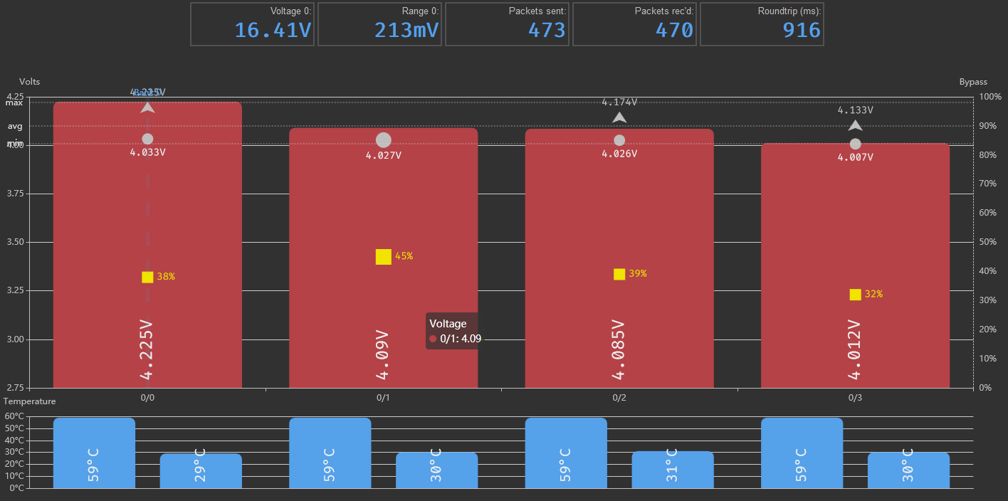
It seems that during balance, voltage measures will fail.
-Will the cables be very thin?
-My Attiny or other HW are bad?
-Other unknown config?
Tested with a lipo drone cell 4s
My config: V440 modules with last firm.
ESP8266 controller.
…
After few minutes draining energy, disconnect modules and reconect. Voltage is now around 3,9 volts and no bypass.
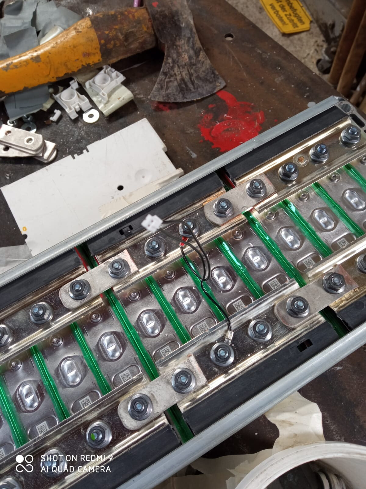
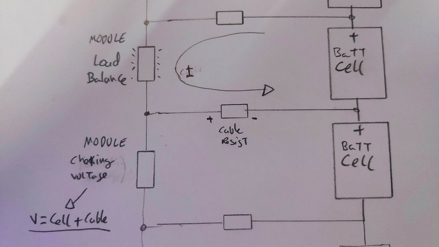
As written here some time ago: Don’t share cables.
Always go with + and - direct from the module to the battery pole.
As soon as one module is starting to balance, the voltage of the + pole is sinking at the end of the cable. But this value is the - of the next cell.
So the next cell suddenly has a higher voltage, because the - is sinking, and if its higher then balance voltage, it starts.
Then the game goes to the next cell.
With the cheap China BMS 30mA and less balance power of them is no problem. But we have here 800 to 1000mA Balancepower.
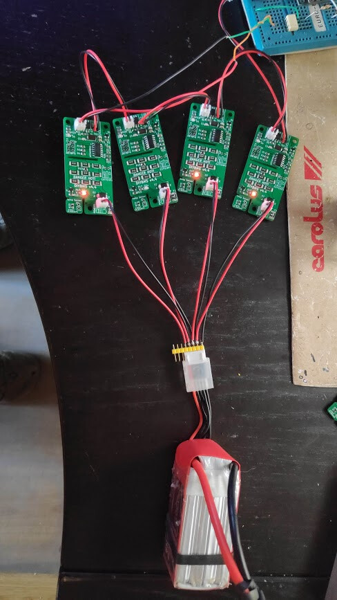
Edit: and we don’t use these red/black PH2.0 JST connector china cables from the picture for powering the modules, they are to thin. For communication no problem.
We use as minimum 24AWG for power connector cables.
Thanks for the advice. I can’t find cables bigger than 26AWG, really PH2.0 JST is too small for the propuse.
On that test, Lipo cables (common part) are 22AWG then 26AWG.
That will be common mistake… Neverless, I’ll tried with real cells shortly.
Maybe this will be arrange by firmware? (stopping balance and check voltage). I’m worried that voltage is down and down without intervention and battery will be maybe drained.
Jst ph2 connectors are rated for 2amps, plenty for the 1amp it may draw.
As a cell balances, the voltage will drop due to ohm’s law and the cells and cables internal resistance.
Yes, I know, you shouldn’t use common cable, but in some environments I don’t think you can do much.
As @dakoal explains, in an environment with common wires, when a module is balancing it causes an increase in the measured voltage of the neighboring module. This causes this module to detect a higher voltage and also to balance. This goes into a spiral that causes the whole system to malfunction and to stop it, intervention is needed: raising the bypass voltage or disconnecting the modules.
I think the software solution would be simple:
-Stop the balancing for an instant in all the modules every minute and measure the correct voltage, or stop the balancing in the adjoining modules.
-Detect that if there are large voltage variations in contiguous measurements and also stop the balancing for a moment.
-Use the lowest voltage in a serie of measurements.
Just flashed the new compiled FW. Works perfect. THX
The issue you have is slightly artificial.
In a normal charge cycle, all the cells won’t be out of balance. So the BMS will then only have a few random cells to balance (if any)
The charger should have stopped balancing well before the cut off voltage, to prevent the situation in the first place.
What you are now doing is more of a discharge test.
Hi @stuart,
Are there news on the Can bus support on the new controller ? What about Modbus TCP ?
I am using the Victron inverter and i setup the 2 wire bms and i am using the relays but would prefer a more inteligents communication between the charger and bms.
/donnib
is there a valid replacement for AQY212GSZ i just had a order cancelled from ali as they dont have them anymore, is the AQY212G the same? thanks
P.S i fixed the new controller i burnt out, c3/4 change and the ic chip and the canbus chip swapped and all is good  aswell as a new lcd and new 8gb micro SD that seemed to be all that went bang