The only problem then it’s that my banks are detachable and fold into place like drawers. I don’t know how i would be able to make a connection between them, and disconnect if i pull one for maintenance, and then it will stop working for the bank still operative?
I saw that the board has two sets of tx/rx connectors. I thought the banks could be connected to the controller independently.
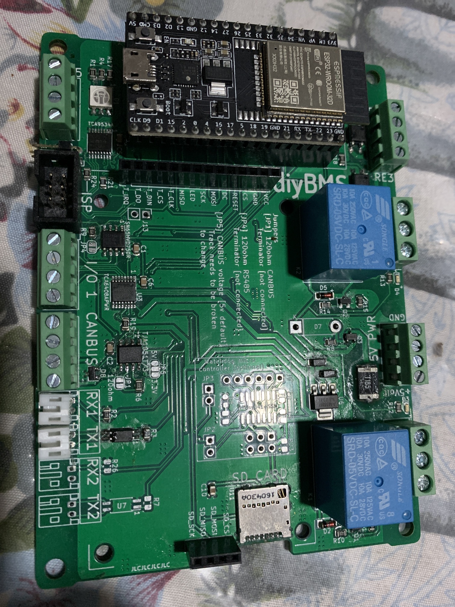
I check for TCA9534A replacement. TCA9554 will be best but I2c adress will change and match with other chipset, so we need to change pinot to fix other I2c adress than 0x20 with A1-A3 adress and modify source code.
I just checked by taking out string 3 and make string 4 string 3 and time out issue remained with the one string… which newly is string 3 instead of string 4.
I replaced module as well as bus cabling but nothing changed…
And i can confirm, it is 16 modules per run which are checked.
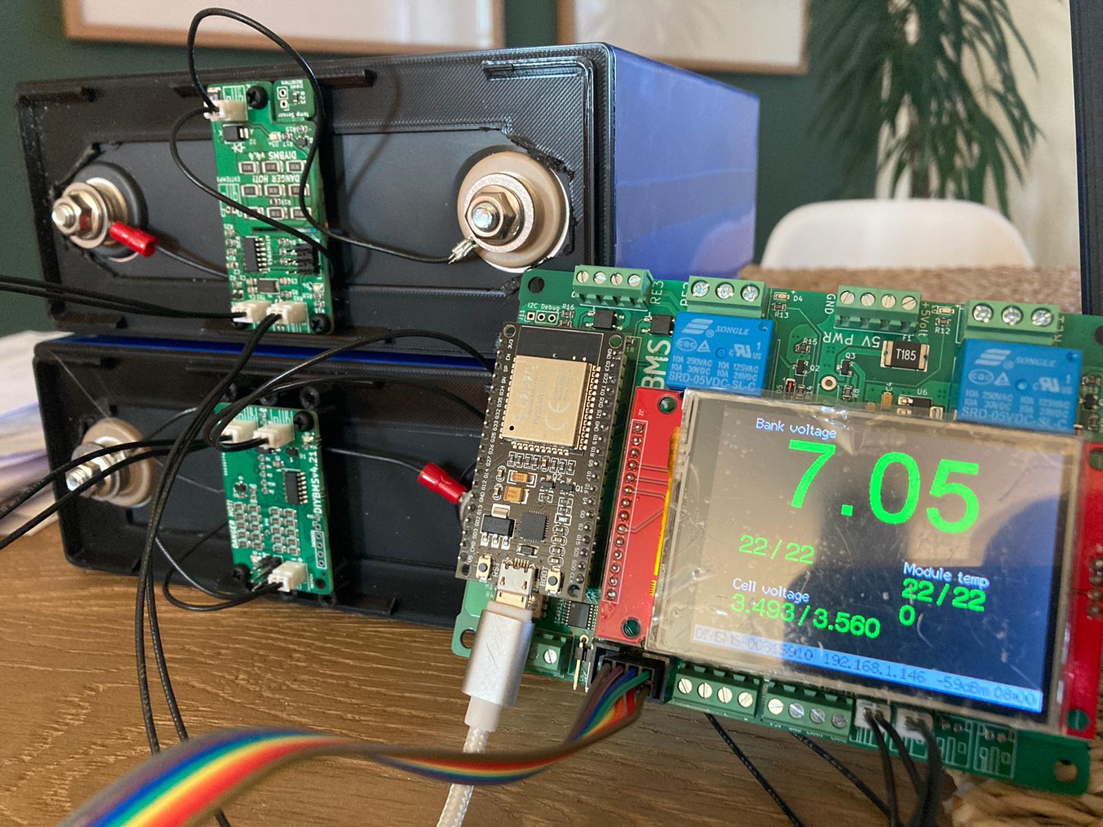
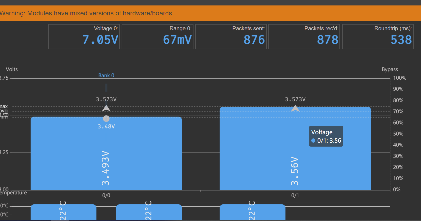
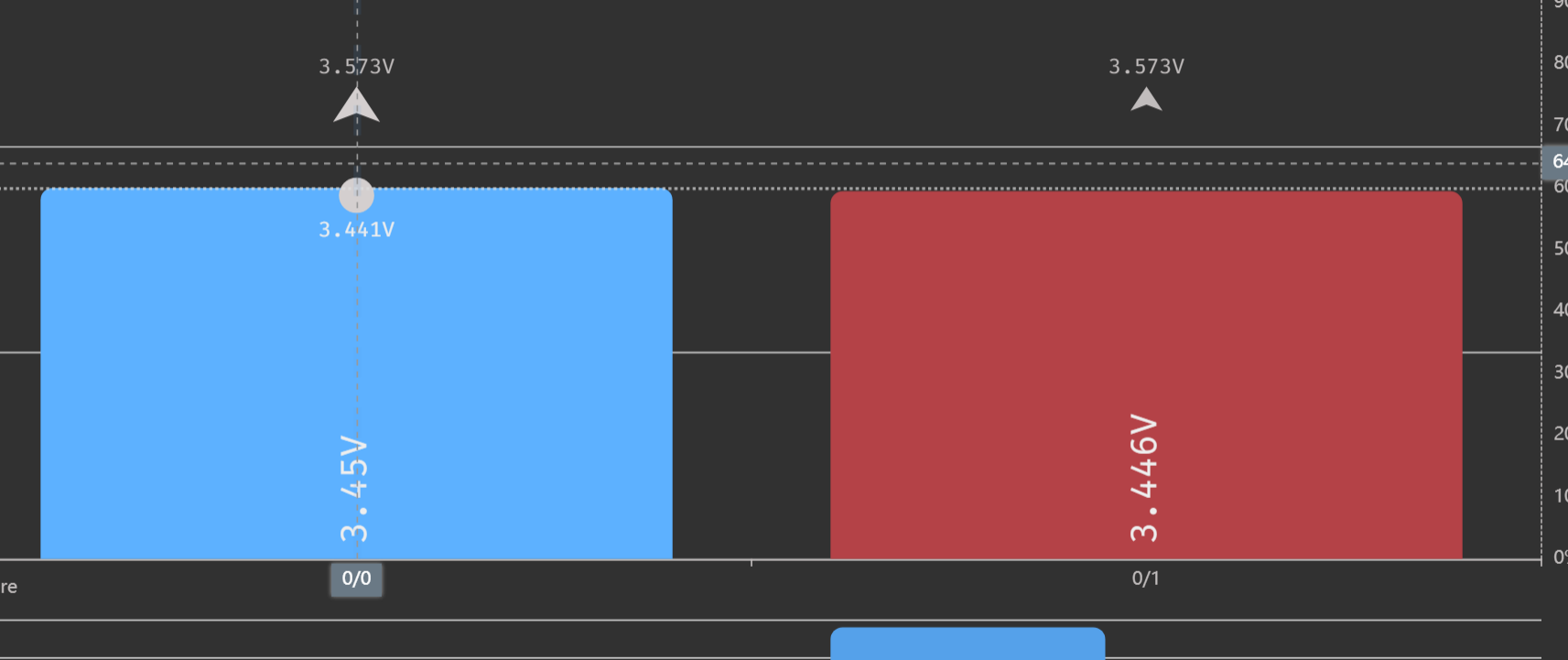
Today testing difference of V4.21 to V4.40 module. Cool that we can mix it on the new controller, and getting an Info.
The main difference is the balancing power.
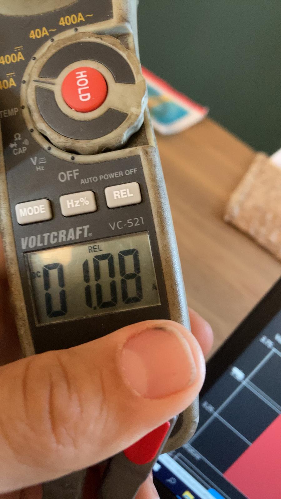
4.40 is starting with 1Amp balance power, when reaching max temperature goes to PWM mode and then jumps 200-900mA
4.21 is starting with 800mA, but holds this much longer (the large amount of resistors results in bigger surface too cool I think)
Then when reaching temperature it jumps between 300-600mA
I will do a long balance test later to look if old or new is the stronger one in long term.
4,40 took 8 minutes to balance a 300Ah Lifepo from 3,55 to 3,45
4,21 took 11 minutes.
Another difference is.
4.40 is hammering the voltage down to the set value (3,45V in my case), and it stands there fixed, maybe one or two times after-balance balancing.
4.21 is doing it also, but still needs “minimal” balance shots of a few seconds.
(after 40 minutes …) and still has 3,455 and not 3,450 constant.
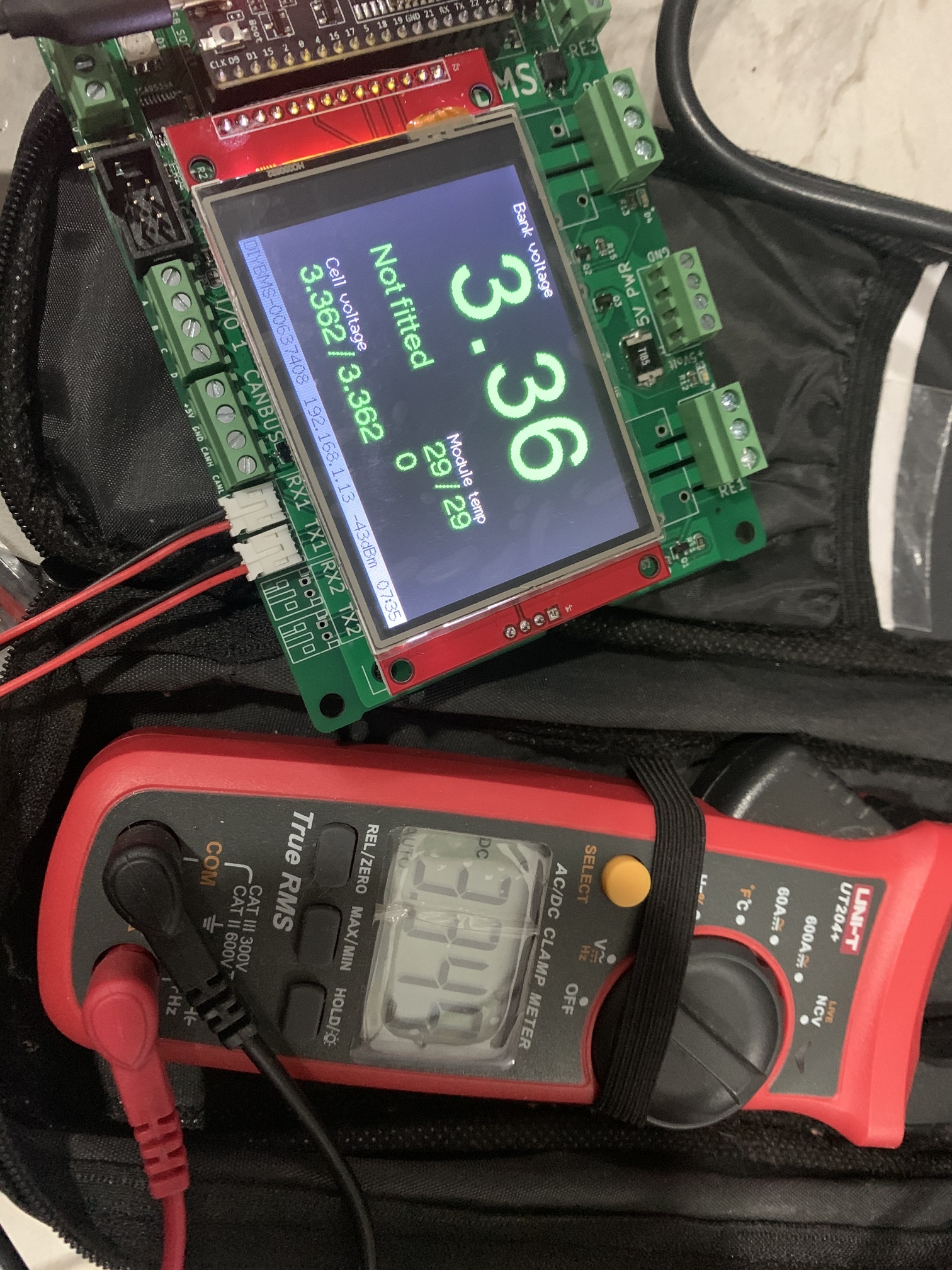
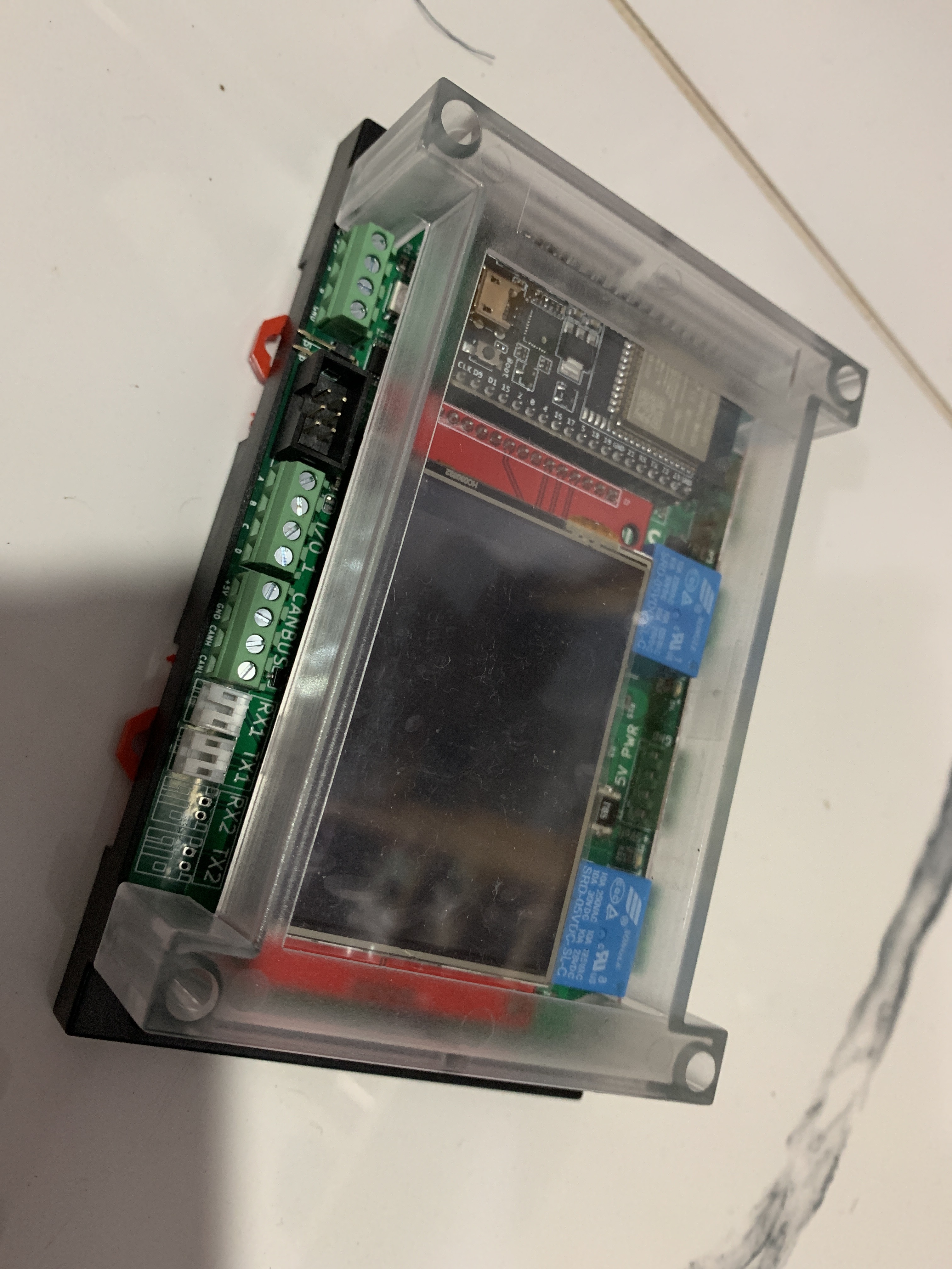
Hello, greetings from Sri Lanka. I built a esp32 controller board and some modules for my LiFePO4 batteries. I half built the controller module from JLC and ordered all the extended parts from LCSC and soldered them myself.
I am wondering if there is any way to send MQTT data to a cloud broker ( I am trying to use hivemq ) with a TLS/SSL certificate. Has any one done this before?