Hi, this is not what I am looking for. Thanks anyways!
Already raised an issue on GitHub. If possible, please look in to it.
I think it is better to add a field where we can select a CAFILE and the code will be able to use the same for data transfer.
Thank you!
There’s no mention of MQTT in that particular thread. ![]()
I now tried to build the CPL File on my own. The PCB File can’t be opnened on my Windows. Already updated to latest KICAD.
An Issue is opened.
Apparently I missed a version update of the controller
full pictures at : TJA1057GT/3J · Issue #83 · stuartpittaway/diyBMSv4 · GitHub
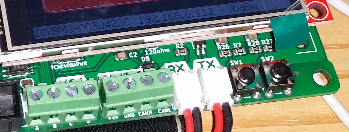
The new controller have push buttons now?
what do they do and can they be added to the old design?
(obvious not as nice looking, they make a contact between A and B, sometimes one can simply solder thin wires with a “lose” button, what will give the same result.)
1 Like
Its a minor update, and the buttons can be easily added to the original board - its main purpose is to wake up the controller screen if you have it in a case. At the moment only 1 of the buttons work - its connects to the J13 connector on the older board.
2 Likes
Hi, interestingly my time out issue has chabged from module 43 to module 33.
It shows wrong voltage and cannot be calibrated…
Regards
Karl
I had some 4.4 modules which I was unable to calibrate - I had forgotten that JLCPCB couldn’t supply and fit D1 (1.25v voltage reference diode).
I kept increasing the calibrate value until it maxed out.
Adding the diodes (which I had in a separate shipment) from LCSC fixed the problem.
Maybe try a high precision multimeter between pin 13 and 14 of the ATTiny. Expect 1.25v.
Ok, I think this is likely a bug.
Can you open an issue on GitHub for this please?
has anyone in europe got a spare 4.2 controller board for sale pre populated with the smd stuff?
i managed to blow mine up very badly, please be careful when flashing the modules if using the leaf version, when you are using the battery to power the controller the isp is no longer isolated power source like when it was done via usb and powered from a laptop
i had it all up and running but wanted to update the module firmwares as soon as i plugged in the isp cable i got a huge bang and all went dead, took out c4 very bad but pcb is fine, just getting no more communication to the esp any more and it wiped out my lcd too  an expesive mistake lol if it aint broke dont try fix it haha
i basially put 48v through it as the ground is common when running it off the battery itself
Hi all !
First of all thank you Stuart for awesome idea! I just order 10 controllers and 30 ‘satelites’ for my project. It ll be preasembled but JLCPCB doesnt have some components so i had to order from Ali. however… I cant find any “TJA1057GT/3” Mayby someone can help with ? Thanks!
PS Im newbie so sorry for stupid questions as what 
Don’t worry about the TJA, looks like a global shortage. The board will work without it.
1 Like
Hi, thanks for response, so can I do not assemble it ?
Add the TJA chip at a later time when available.
You can build the remaining controller with the other parts.
Nice to hear that, thank you so far. I’m waiting for delivery. Have a nice evening.
If anyone is interested, I have some YouTube videos of 18650 and 20700 based power wall using the DIYBMS.

Something screwy going on and I’m not sure what is causing it but it’s costing me a lot. I have now had 5 cell monitor boards (v4.21) and 2 wemos d1 mini boards be destroyed due to some kind of power surge. I have 2 separate controller boards one with 3 banks of 14 cell monitors and the other with just 1 bank of 14 cell monitors. I went to put them all together on a single controller board but when I connected the last TX cable to the RX on the controller board (it was on at the time) I got big arcing and the magic smoke came out of the D1 mini and the cell modules at the start and end of the chain. All dead. Luckily I had a few spares so replaced the cell monitors and the D1 mini and got it all connect and working. I had been thinking about what could have caused the arcing and wondered if the new location of the controller board (now next to the inverter) was causing the issue so I decided to move it back to where it was. This time I unplugged the D1 mini from power and disconnected the TX and RX cables, moved the controller board back to its old location and reconnected the TX and RX cables but when I went to connect the power back to the D1 it arced and blew another D1 and another 2 cell monitor boards. I’ve run out of D1 minis now so have had to order some more and I’m rapidly running out of spare cell monitor modules. I can’t understand where this arcing is coming from. I’ve never had any trouble before.
Why don’t you measure the voltage between the points you’re going to connect, before you connect them? If there’s an unexpected voltage, investigate further before making the connection.
It would seem that some part of your installation that you think is, or should be, isolated, isn’t and that’s where the problem lies. Or maybe, there are multiple faults - just because two things are the same is no guarantee that both are correct.
Hi, I am thinking of adding MOSFETs as a switch to the battery instead of a relay. It should be a bidirectional (back to back MOSFETs) because I got running a Hybrid inverter which handle charging the battery also. This has to be something like common port BMS.
Is it possible to add two of those spot welding mos boards available in Aliexpress?
Something like this:
Well as I understood it the Rx on the controller board is opto-isolated so I wouldn’t have even thought to check the two pins before connecting the comms cable from the Tx of the cell monitor to it. Checking a comms cable is not something you would normally do before connecting it, yet when I did sparks flew and things died. I am powering the D1 mini from the battery directly using a buck DC converter. Do you think that could be the issue? Having said that, I’ve been running it like that for a year till now without issue. Can’t understand why suddenly something is different.