Stuart, what thresholds value do you recommend? The float value, between absorption and float, equal to absorption or higher than absorption? I am a little worry about these values because I think that the module can be affected if they work for a long time.
Thanks in advance.
Thanks @stuart .
One thing I’m quite puzzled about is the cells and banks.
100 units is a lot.
But I don’t understand their setup.
Sure, I understand series and parallel cells.
I doubt I can use on a 3P 3 cell modules and have each module seen as individual components.
Being paralleled, the 3 cells will show the same Voltage.
One thing that can differ is the temperature per module.
More cell modules would give more balance power.
So I see that I can configure the number of cells and the number of parallel, but no idea on how to set this up in real life!
16 cell modules TX to Rx, and controller TX and RX is clear.
32 (or, 48 or 98) cell modules…
That, I can’t seem to figure out how to do.
Alternative is 2 (or 3, 6) X 16 cell modules where each have its own controller.
The relays of each controller can be set in series, so each one of them can control the main contactor.
I don’t have 96 modules, just 80 cells, in S16P2 280ah and S16P3 152Ah, total 1016Ah
The route of 2 controllers is now my idea.
Cell modules I might have extra can be “double” installed (one have TX/RX, one communication disconnected) to have additional balancing power.
I really like the new controlers, especially as they have canbus now.
(So do my hybrid inverters)
This week I’ll try to order from JLCPCB
Probably will ask a few questions about alterative components as JLCPCB doesn’t have it all on stock!
The banks and modules map to series and parallel setups as you mentioned.
There isn’t a benefit to monitoring individual parallel cells as they will all be the same voltage. The temperature could vary, but I don’t think there is any other BMS on the market with as many individual cell temperature monitoring sensors as the diyBMS
1 Like
I thought it might be a long chain like 64 modules, where you move the cells to a bank you configure, each being 16 cells, 4 banks.
Problem I’m afraid for there is that if one module fails, you lose all communication, need to test 64 cells before it’s up and running again.
I don’t know how often a cell module fails.
(Feedback please. How many of you needed to replace a cell module after installation where all was working OK???)
During my build, I lose about 20-40%
20 with attiny soldered by JLC, 40 when i do myself.
Most of them I can program, but then have issues with short of +/- or communication error.
That last is the most, where I tested the contact from the TX/RX connection wire to its solder point on the PCB. That’s OK.
Really strange.
Some have the 3 legs thing close to the TX/RX half lose (soldered by JLCPCB) that probably is the reason for those.
2 show the red light, and no communication.
Probably just my standard bad luck I have with electronics.
I’m really good in getting errors 
(Solder joints I made where checked with microscope and multimeter.
Not all joints, as I thought to be able to thrust the solder from JLCPCB)
Hi there
I have a most of the stuff for my build but the usb flasher hasn’t arrived yet been impatient to start
Is there any other way have raspberry pi Arduino and a TTL to usb for example can any be used
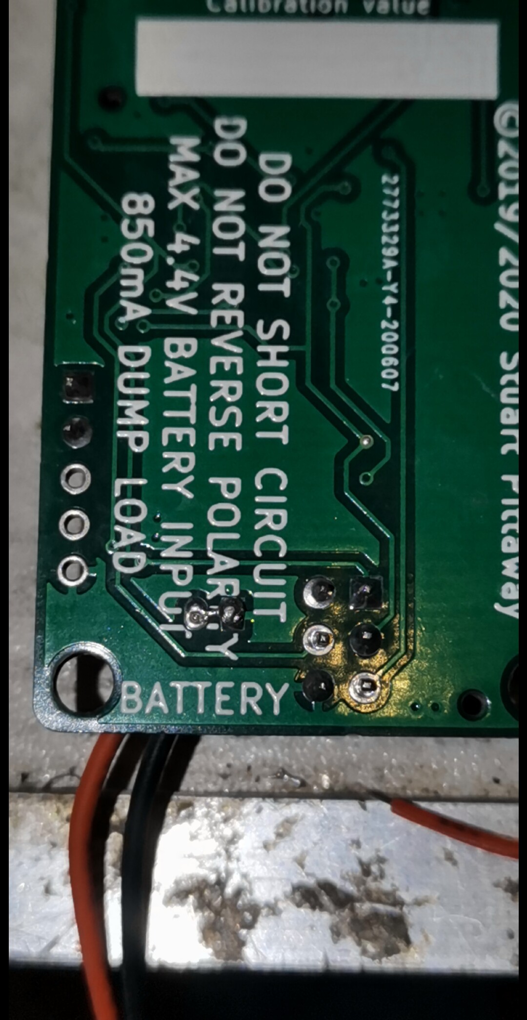
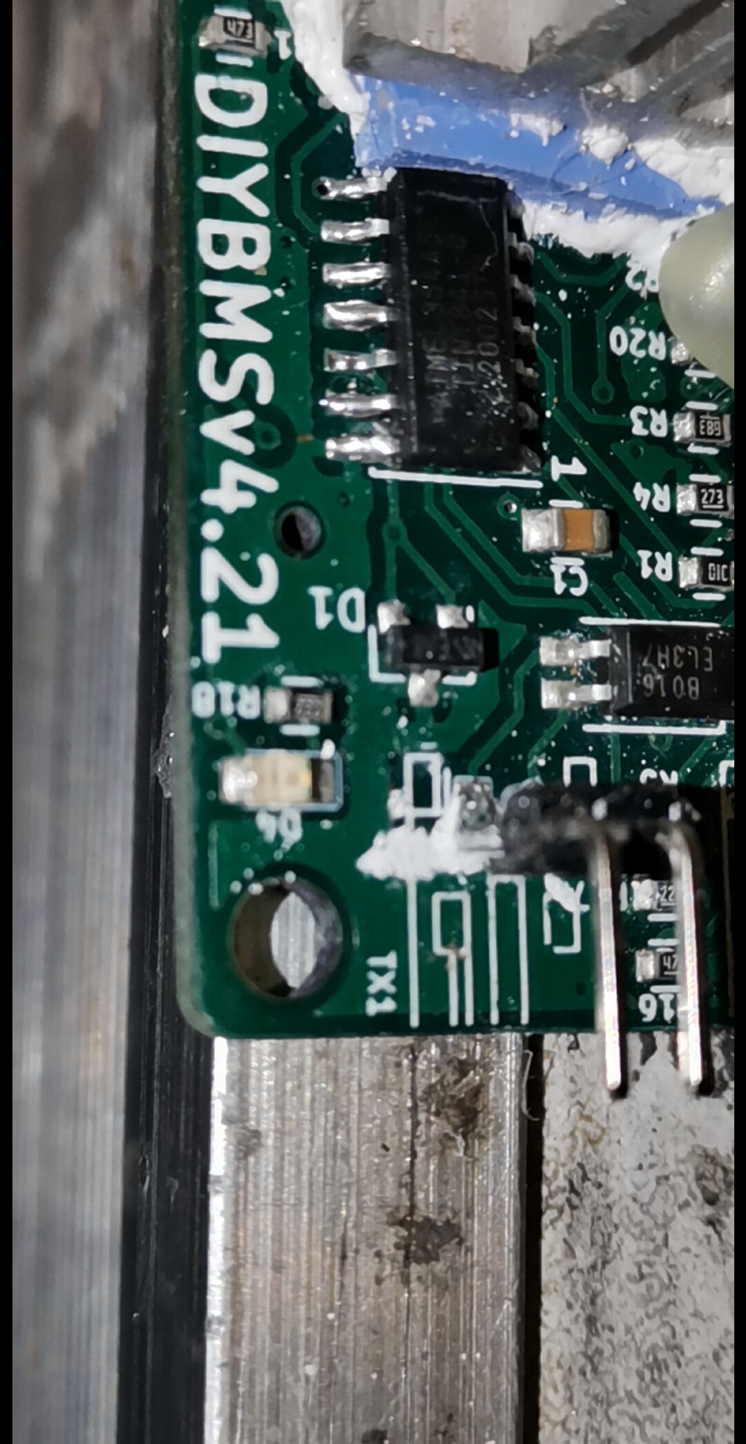
For the cell modules, V4.40, most parts are available.
D2 (SMBJ5.0A) I swapped with C10204.
Part AZ432ANTR-E1 (lscg C84139)
I have a hard time finding a replacement for.
Suggestions, please!!
Would AZ431LBNTR-G1 be a good replacement? Lcsg C154868
Almost the same.
Except 1.24v and 1% tolerance instead of 1.25 and 0.5%
Don’t swap that part, it’s the best one to use. There is an entire forum thread on problems people have had with swapping that to an inferior part.
If they are out of stock, please wait!!
1 Like
Thank you Stuart.
Of the 60 cell units I’ve ordered/made, I have now 31 operational.
9 who seem to work, but don’t give information into the website.
All light blink as it should.
Except one, who have blinking red after a short time.
5 have somewhere a short, if I measured +and - there is contact.
12 that have connectors broken or bad contact
Due to circumstances I ended up with 1.25 JST, and impossible to get good ones.
First month’s of Covid an order from China took months (4) to get to Thailand (usually weeks).
Local stock unavailable.
They where too thin to be strong.
After this I used standard pins, 2.54, that went a little better.
Hot glue seems to be the best to strengthen the contacts.
30 had the attiny soldered by JLC 30 by myself.
3 x attiny I couldn’t program.
One of the reasons to really want the version 4.40, hopefully more robust for hand soldering!!
the attiny841 was in stock today for 5 minutes xD
1 Like
Nothing special.
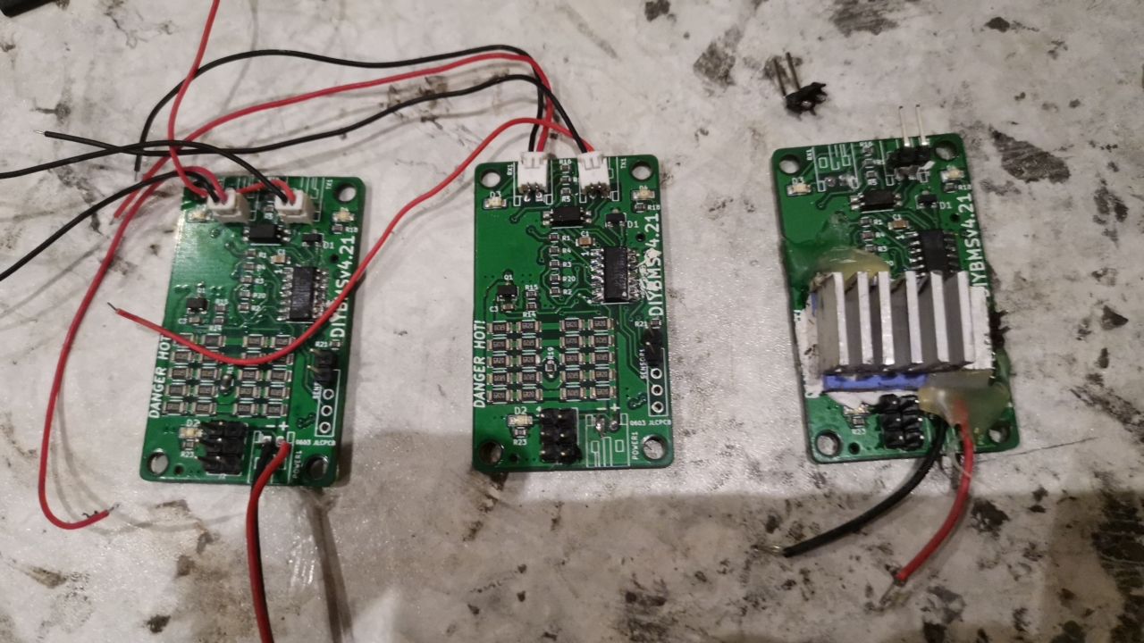
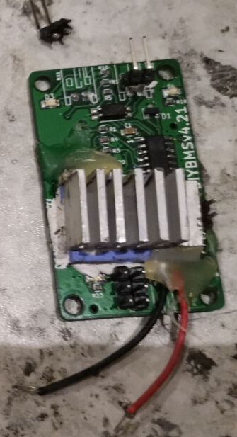
Soldered attiny, connectors and added aluminium I had available as heatsink.
This is after cleaning with 99% alcohol.
The others look the same.
Soldering joints look surprisingly good
The purple is soft heat conductive pad I used in the past on video cards and had left over.
Besides this, I used heatsink paste.
There aren’t any holes to mount.
A clamp on the sides would block the temperature sensor contact.
I for sure wish JLC PCB would solder JST connection.
The hooked types cost a fortune, if available at all.
JST in overall expensive.
Except when buying a set of wire, plug and socket. Then $ 0.05 (in a set of 50)
Socket alone easy $0.25 (set of 50)
Amazon charges between 15 and 45 for transport and tax to Thailand.
8oz ox-gard cost me $45,-
No local alternative. At all.
With Chinese sites offering very limited options, and western sites charge extreme transport costs…
I’m just out of luck.
Add the Covid delays of several months to obtain parts and living off grid with no functiona BMS, you need to work with what you have and get your hands on.
If paperclips would have fitted and be flexible enough, those would have done fine
They aren’t.
2.54 pins can be soldered and provide better contact.
2.54 female sucks for contact.
At least the ones I received from China.
No grip and bad contact.
With those as option… I have a lot of defective units.
The 2.0 holes are so small that solder sucker and braided copper don’t remove the tin, no new fitting.
Best I can do with the failed 1.25 and 2.54 females is to solder wires against the small tin bulb, and cover it with (non conductive) hot glue.
It works, gives the contact, most of the time.
Now… almost 9 months later, still not a working system.
I have 60 or so programmed attiny, I can de-solder them from the 4.21 boards who are way to small, and solder back at the new boards.
I might get 32 X 4.21 working, what is my minimal need for the cells.
Knowing my luck, I need to also install the new version and controller as for sure it will fail.
The new version i’ll order 50 PCB and hope to end with 32 working and a few spare.
Probably just order 40* attiny extra, and if they aren’t enough, use the ones from failed 4.21.
To bad other companies ask tonnes to make populated PCB,
And to bad JLCPCB doesn’t do all the parts.
That is very kind, but I am in the Netherlands, so not sure if that would work out with postage,
I will keep your kind offer in mind, certainly if there are more folks who want to join
Yes, I have used avrdude and the precompiled files - and it looks the same. avrdude DOES report the fuses as listed in the file, so I’m fairly confident. And I know it’s doing something because it flashes D4 at power-on, then flashes D2 every few seconds. I am concentrating on one module, though I did try two just to make sure the first wasn’t bad.
I have a fair amount of basic equipment, including an oscilloscope if needed… I haven’t done anything yet apart from soldering, flashing, and testing the cables, since the batteries these are intended for won’t be here for a few weeks yet… just testing with a single 18650 for now.
Okay Jeff, sounds like you have the basics covered. On the JST cables, you have pin 1 to pin 1 and 2 to 2?
If you use one of the JST cables and loop TX to RX on the controller (no modules connected) do you see “ignored errors” in the web page?
Thank you so much, I tried with utp and ftp wires, but the errors continued, now I use a shorter wire and everything is fine. Thank you for your attention
Thank you so much, I tried with utp and ftp wires, but the errors continued, now I use a shorter wire and everything is fine. Thank you for your attention and congratulations for you amazing job.
Yes, pin 1<->1 and 2<->2 on the JST. With no modules connected, I do see “ignored request errors” climbing for every packet sent by the controller. I also verified that both the JST cables exhibit this behavior - so that’s helpful.
Great, so that means the cables and the controller are working as expected.
Work in 1 of the modules at a time, there must be a dodgy soldering joint
Hello All, I am tracking this project for some time. It’s really great job, congrats, especially to creator & invetor and all the contributors.
I saw on the forum reported issues about communication problems. Are there any plans to switch to RS485 to fix it ? I saw in the newest controller board RS485 but the monitoring boards are still having only RS232.
Thanks
JB