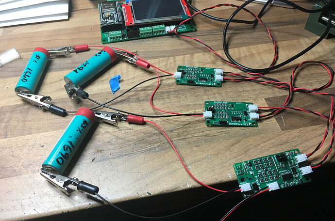
Where did you find that cable for connecting the module?
That was a freebie I sent out to patreons, along with a sample v4.40 board.
I can put the design on GitHub if you want it.
It was cheaper to make that than to buy ribbon cable, not as flexible though!!
Programming becomes so easy now, do you have a TFT screen?
Sure, I can order it in my next batch of PCBs. Perhaps order a bunch for other people who might want them in the US (similar to the controller PCBs).
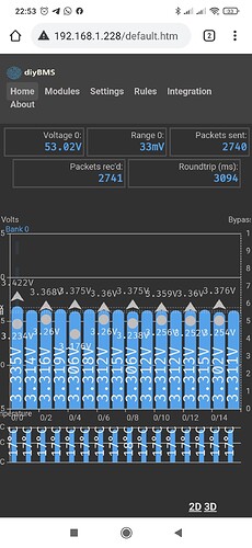
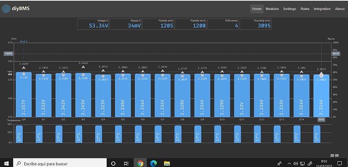
I realise that the errors appears when the multiplus II work with high charge or discharge.
At night the errors are not shown
not at the moment
Ok, on the controller what value is the resistor R2? Should be 2200ohms.
You could make the communications cables shorter as well.
Hello Stuart, R2 is 2200ohms, the strange that errors appears when the charge/discharge is high. What is the difference between oos error and crcs errors?
At the moment everything works well, at night
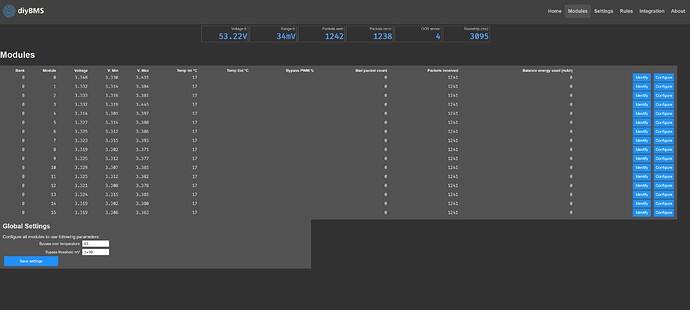
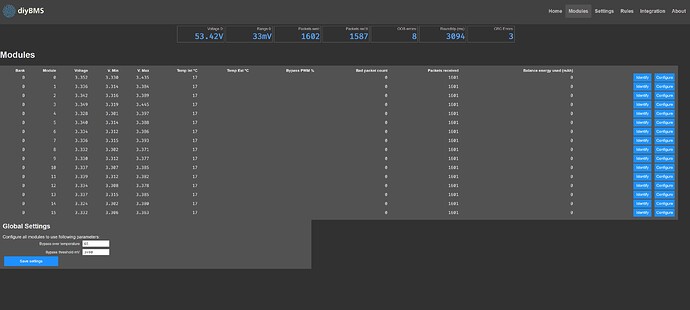
Can you show me a screen shot of the modules page?
Out of sequence errors (oos) means that a reply was lost, it never arrived.
CRC errors are received messages but they are corrupted.
I suspect there is a module or two which are causing the trouble, hence the need to see the screenshot
Ok, none of the modules report an error which is great.
There must be an issue with the cable from the last module back to the controller. Check the jst plugs and sockets, and try and route the cable away from the battery
Thank you so much Stuart.
Its quite common issue on communication like above. Where high current/charging/discharging causes more noise in the area than low current does. Due to the devices used.
Common practice is to make sure connectors sit as they should. Make sure they are evenly twisted all the way between the contacts so you dont leave anything out. Just 10-15mm will cause difference here.
And by looking at your picture you for instance have a wire that isnt twisted at all. Looks to be the last node that Stuart pointed out have issues?
I’ve ran a couple of charge/discharge cycles and the bms struggles to keep the cells balanced (I know it’s a runner cell but was testing the bms balancing). What temperature is ‘safe’ for the temp bypass? I seem to hit the default 65deg quite quickly during balancing.
@garethb
Balancing should only have to be activated when a cell have drifted. Always start with a full charge where you let the cells balance until 100% even. This can take hours or even days on larger systems.
The cell modules itself will not be able to continuously bypass with a 100% duty cycle value due to its cooling capability being passively cooled. . If you need higher duty cycle you need to actively cool them down.
I cant tell for sure what duty cycle they can hold at different temperatures but personally i think max temperature on the 4.2 and older boards should be around 60-65C. This without any scientific tests or looking into them  And with that said i guess the duty cycle is halfed perhaps?
Neither less do a full balance cycle and see where that takes you. If you need to balance that hard as you say every cycle after a full balance you have cells that are way way off 
Im running tests right now about adding a small heatsink and also a video about how to add small fans to them. Will post the link here when done but it will take another week.
On wifi note. It happened at least three times now on various occasions - when I decide to reboot my raspberry pi AP I need to restart wemos as well (which I forget sometimes) as it doesn’t reconnect to that access point. Could do some thorough testing at some point but for now I need all data send to influx db to learn out how each cell is behaving.
I changed the WIFI code a few months ago to solve a problem with the controller rebooting when it lost WIFI. The current code should attempt to automatically reconnect if WIFI is lost. Are you using the latest code on the controller?
It is 2021-02-11-12-05. But just did another reboot and everything went fine so will come back if will find out how to replicate it properly.
I added this yesterday, diyBMSv4/ProgrammingAdapter at master · stuartpittaway/diyBMSv4 · GitHub
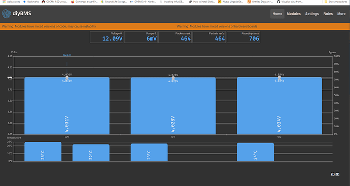
I have combined 4.21 with 4.4 modules with the new controller (I bought a screen on Amazon, to see it like that, pretty Stuart, hehe) and everything seems to be going great. I have to do some more testing, a slight warning appears that there are modules of different versions, but it is an orange not red warning.
By the way I have unsoldered the thermistor and I have attached it to two cables, I like square things and I was sorry to break the board. but the idea is good for people who do not know or can weld.


