Yes, did the jumper trick and watched in VSCode. It says PFC on 0x20, then not fitted, a few other things, then repeats “Error State = 4” ad naseum. The web interface shows the new error message. My chips appear to be labeled PCF8574T.
I am sorry to be back with the same question that probably was there before. I thought it is an issue with controller itself but I finally switched to another one that is working fine, but the issue is the same.
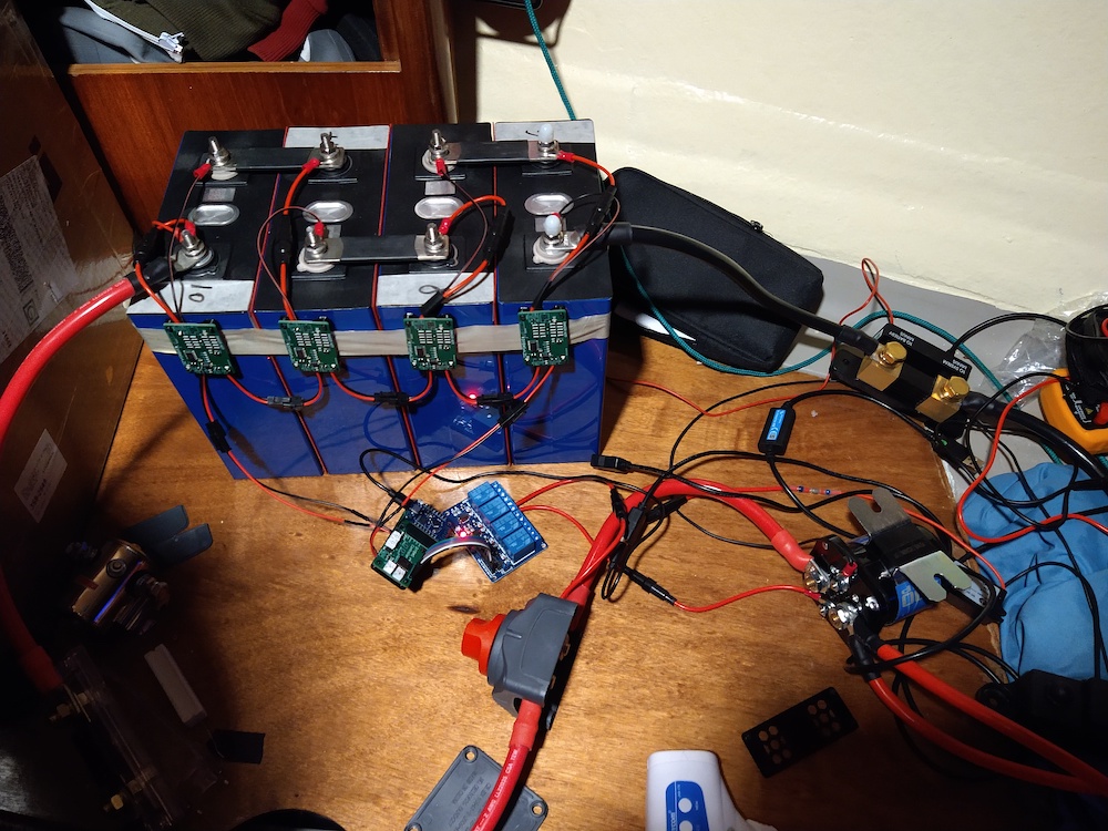
The setup looks like that. I have noted that spinning cables help but there is no issue when there is no load. When the load is about 60-70A from 4S pack it starts to throw an error “The controller is having difficulty communicating with the cell monitoring modules.” so I switched to external power source for controller and it kind of went back to “ok”, but when I increased load to 120A’ish it even started throwing an additonal one:
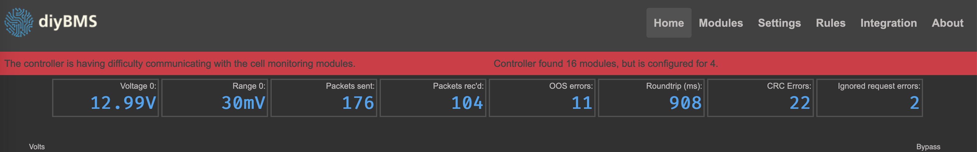
Though there are 4 modules for sure. And the LEDs on modules and controller seem to blink fine. It feels like inverter is drawing to much load and modules do not get enough? Any ideas?
communication wires not twisted
Ok, I’ll take a look at the code later on and see if theres a bug
2 Likes
This will certainly help, along with twisting of the power wires to the modules.
They look short cables though which is good news.
When did you order the controller board? There was a change made a few months ago to change one of the resistors for a lower value, which helped resolve the comms issues. It appeared that the controller and modules would send data (all the green LEDs flash) but then the controller had a problem receiving the data at the end. Sounds similar to what you are seeing.
The order was at the end of June, 2020.
Ok, thanks, will try to twist as much as possible though it will be hard with short comm cables but I can always make them longer.
Before you bother changing the cables, take the ESP8266 out and look at the resistor marked R2 on the controller PCB.
If its marked 4701, then its the old value, and should now be a 2.2K resistor.
Do you have any of those? Even a through hole/wire resistor would be fine, just need to unsolder the R2 part and then attach the legs of the resistor to the small pads.
Yes, it is 4701 on R2 and R4 and R5. R3 already has 2200.
Should it be 2200 Ohm https://www.amazon.com/uxcell-Resistor-Resistors-Tolerance-1000pcs/dp/B07QDL2CVC or https://www.amazon.com/uxcell-Resistor-Resistors-Tolerance-200pcs/dp/B07QGSW4Q1 220 Ohm?
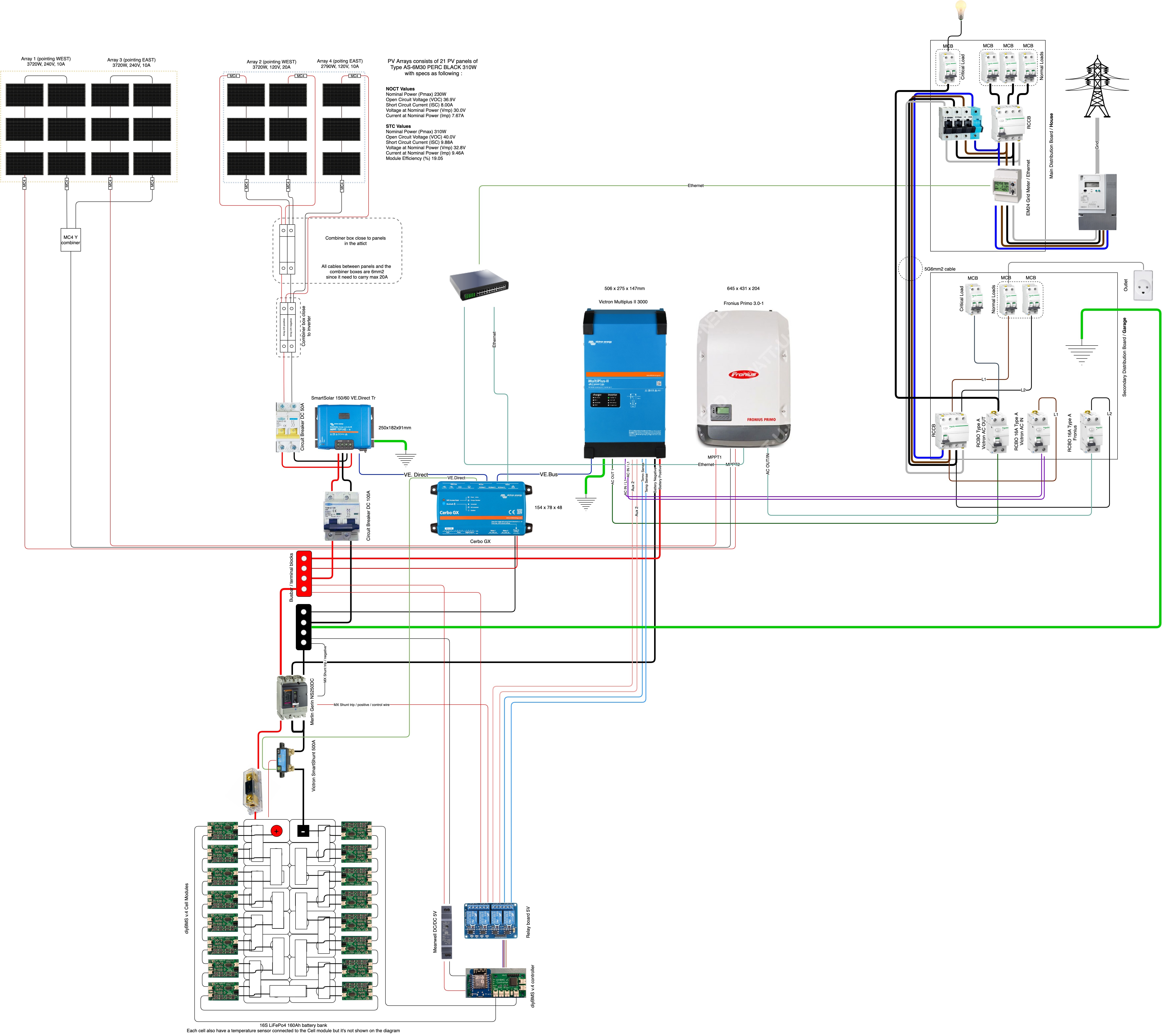
I added the schematic for reference.
The 4pin connector, J2, has comms and power. Pins 1 and 2 go to the opto coupler while pins 3&4 go to a ring lug and bolted to the ‘common’ center bolt.
The leaf cell is a 2S configuration and the common is the -ve for one cell and +ve for the other.
Assemble you cells in the format you need, xSxP…
1- build the cable, secure to common bolt. It is easier to secure the ring connector before you attach the boards but that is me.
2- mount a monitor but do not insert the 4pin cable yet. The main mounting holes are marked +/-… Make sure you respect the polarity. With a basic 14s1P arrangement for 48volts you will be flipping the batteries for a series arrangement. This means the leaf monitors must be flipped also (respect the cell polarity).
3- with only one leaf monitor mounted connect the 4pin cable. Without any other connection for the comms the 2 leds should flash waiting for connection to the controller.
4- if all is well the you can connect the comm cable to the controller. The comm cable on the 4pin connector goes to the RX connector on the next board in the daisy chain. For a single board test it goes to the controller Rx while the leaf board Rx goes to the controller TX.
It is a bit confusing but it does work.
MAGIC SMOKE issues.
DO NOT Ever EVER insert the 4pin connector without the ring connector being bolted to the center battery screw. If you do this when the pcb is mounted to the battery you power the board with 8 volts and kill the board… How do I know this… 'cuz I was careless and poof went a board.
diyBMS-Leaf-schematic.pdf (550.8 KB)
1 Like
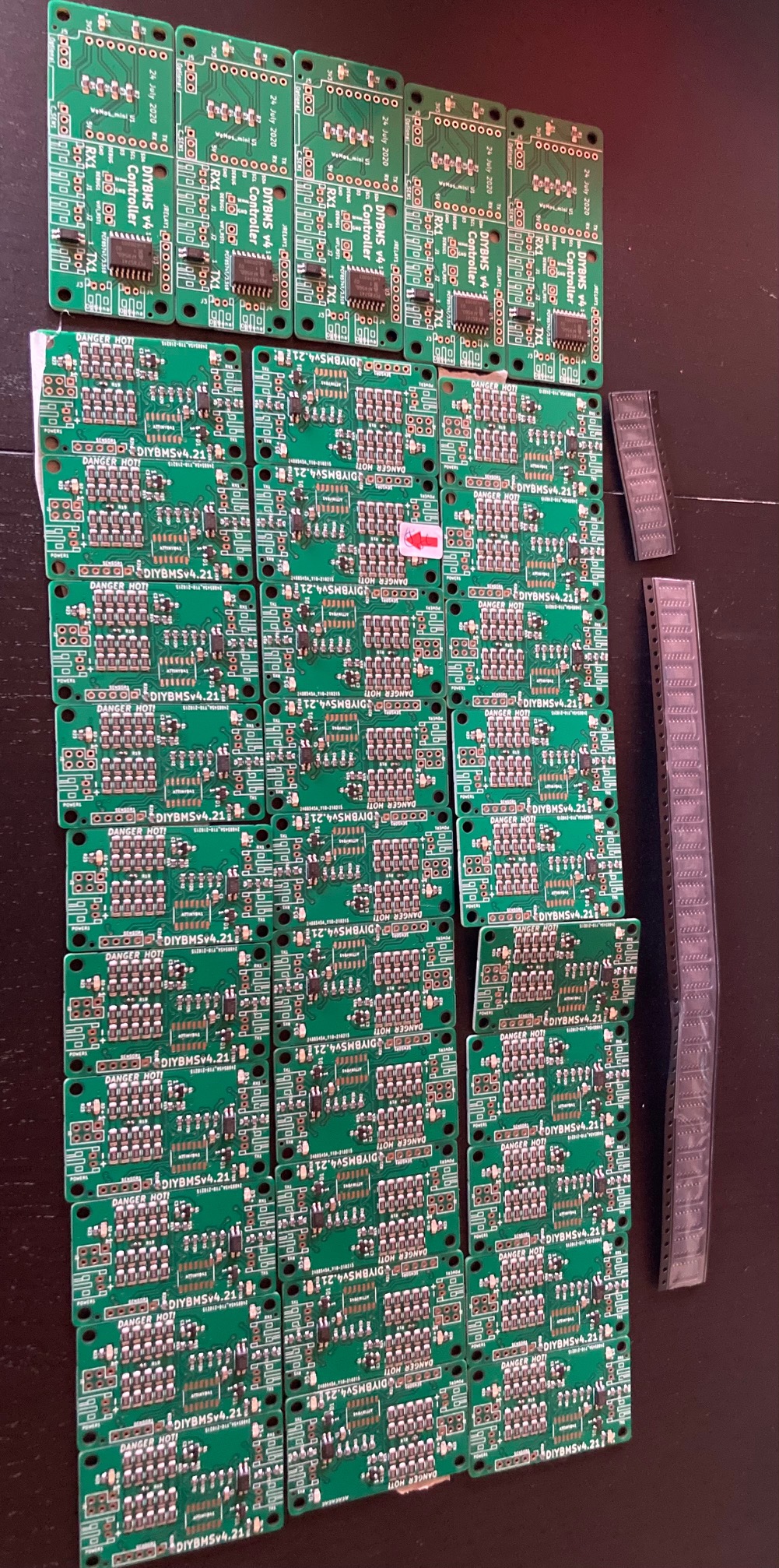
So, I got my boards and the chips (attiny841) only waiting for the connectors.
I am not going to need all of them, so 3 controllers and 20 cell modules are for sale (I live in Belgium)
Anyone interested ?
3 Likes
Is it something I have done, or is the 440 version of the boards quite a bit more expensive than the 421 version of the modules?
If you had an alternative for the out of stock ATTINY841, what would it be?
It makes sense that if I were to have my order assembled to have all the surface mount done.
I don’t have a hot air station nor a fine tipped iron.
Hello, do you use bms with two signals? Could you share the values of bms and charging parameters in multiplus? Thanks in advance.
It is more expensive, it has more components.
The attiny841 is often out of stock, no equivalent part exists, so they need to be hand soldered.
Hello - have you implemented this schematic already ? Could you tell me where to find more infomation on how to trigger charge / discharge on the Multiplus + how the Merlin Gerlin is controlled ?
Hi Stuart, can your BMS work with LiFePo4 cells? Is it needed to change something in the code? Or do you have provided adjustment parameter for this case?
I would like to say your work is amazing. Thank you very much. If I go to make one pack with you BMS I will use your code on JLCPCB so I can help support the project.
Thank you in advance.
Yes i have implemented the 2 wire BMS to the Multi, i have not bought a coil for the Merlin yet so that part is on hold. I am not sure i would ever do but will se.
In regard to the 2 wire BMS you need to setup the Multi with VE.Config / ESS / chose 2 wire bms during the setup and select which input you use and how the multi should react to those eg. should it disable the charger or go into floating when BMS tells it.
What voltage range are the cells you are using?
The normal LiFePo4. They charge to 3,6V / 3,65V and do not supposed to discharge more than 2,5V.
Should be fine then. You can calibrate the voltage and set the balance levels in the configuration.
Perfect! Thank you!