No problem, I got the wrong end of the stick 
I wouldn’t have expected a light bulb to crash the modules though.
No problem, I got the wrong end of the stick
I wouldn’t have expected a light bulb to crash the modules though.
Marius, that’s correct, 5w bulb as a load on the battery (Think I confused Stuart buy getting Cell/bank/battery/load mixed up).
I always planned to use a buck converter, and hang the losses.
I’m intending to replace the 12v battery (Lead acid) on a motorhome with a 24v Li-ion battery assisted by Stuart’s BMS for balancing and reporting to Grafana etc.
This requires some work to the vehicle to disable the 12 lead acid charger (mains powered), and disconnect the Alternator connection to the leisure battery. All relatively easy given planning and forethought.
My solar controller will charge 12 or 24v Li-ion batteries as is, and 7s gives closer to 24v then a 3s or 4s gives to 12v.
Therefore the charging side is solar 24v, the discharge goes thru some buck converters (loads of them available at the Amps I need) to supply lighting (12v LED) and other low wattage devices.
A 24v inverter is connected before the buck converter, and away we go.
I guess that’s grafana? I’m playing with it now, and struggling to get the ‘over time’ readings. And total up of numbers. That’s for another post though.
Antel: Did you get your “Failed to save” issue resolved? I tested all my boards last night and they all worked perfectly with this exception. I have a 5 ohm 5 watt resistor and I cannot save the load settings - I get the same “Failed to Save” response. Thanks!
Stuart: AWESOMENESS!!! I connected my boards last night to some small battery packs and it worked perfectly. All the videos by you, Gelisob, and Rick made the process much easier. It is embarrassing how much information that I ignored when watching the videos multiple times and then after the project is finally completed the “light bulb” goes on and I finally understood much more.
Has anyone on this blog connected the DIYBMS via a jetpack and port forwarding? My batteries will be at a remote location (on a boat) and I want to check them remotely.
Thanks again everyone and especially Stuart! I will post pics when my batteries arrive and the BMS is setup.
@stuart correct, but thanks @marius_r for the addendum as that helps me understand the basics a little bit better.
Gotcha, so I take this to also mean that there’s no on-board overdischarge protection, and thus if I wanted something like it, I’d require a separate relay/contactor.
Likewise, this state likely occurs during charging, so this behaviour is akin to post-balancing overcharge protection?
In any case, I’d like to experimenting with these in a DIY stand-up electric scooter and I think these boards + some additional components on the charging and discharging circuits might give me what I need to get started with something simple.
@malabarmcgyver My fix for that was to try a different browser. I was using chrome. I tried silk on my kindle, and it saved fine.
Thanks Ianzecki! That sounds logical. I will try that tonight.
Jeff, just close and reopen the browser.
There is a repy for that from Mario as well (see below).
There is XSS protection in the esp-code. When you have the page opened and reset the esp, everything work except saving settings. Simply do a hard reload and it works again.
Regards,
Mario
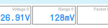
Can someone explain why I’ve got 128mV imbalance and no balancing is taking place? It was working a few days ago. Well it was discharging cells the balance range was around 40mV at worse.
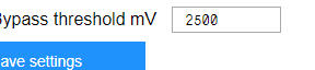
And I cannot reduce this below 2500mV ie 2.5v. Or has my head stalled?
Thanks in advance.
Or will it only top balance?
It will only top balance, so if you charge the cells up they will balance - set the Bypass threshold to the level you want balancing voltage to begin at (probably 4.10V)
I apologize - in advance - for my ignorance of the applications that are being proposed for monitoring and for the questions that are more focused on the ESP8266. I attempted to port forward my Verizon MHS900L, but it appears that it is not capable. If I purchase a jetpack that is capable of port forwarding, do I need an Arduino with Home Assistant installed in order to upload the data to InfluxDB/Grafana? The Grafana is nice, but I would prefer simplicity - without the added Arduino. If I can just monitor the ESP8266 over WAN, that is all I need. I am not asking someone to tutor me on “How” to do this - I just want to know if it can reasonably be done before I purchase another jetpack. Thanks again for all of your assistance.
Please don’t port forward to any esp module. They are not security hardened and you are asking for trouble
Since this is my first time trying to figure out how to solder a board, I think I have everything correct but can anyone confirm the LED polarity?
The LED’s have a mark that points to one side which should be the + and should point to the top of the board if you’re holding it up? Also doesn’t look like the capacitors have a polarity?
No doubt i’ll blow them anyway since they’re stupidly tiny and I’ll end up reversing it but you have to at least try once… or 10! I’m sure it’s part of the initiation! 
Ahh! “Bypass Threshold” My bad.
Thanks Stuart
Paul,
The caps have no polarity The LEDs in your Pic are around the wrong way. Negative to the top. It’s there in the gerber files, but gets lost when the boards are made.
Where did you get that pic?
My LEDs have a green marking at the minus pol. In your picture you have the wrong polarity. With a simple multimeter you can also check the polarity of your LEDs.
The picture is from Stuart’s youtube video. I just paused it and took a screenshot and marked each component so I could get a visual of where things went. I’m not too good at schematics, lol.
So the all 3 positives are negatives? Well it was 50/50 i guess and since I got them both wrong then technically I still would’ve got it right ! (I knew that really, just testing… honest) 
I’ve ordered one of those tweezer testers too so hopefully it’ll make placing them easier. I was a bit put off at building them but the picture helps so hopefully I can get all 7 built soon.
Thanks to you both Simon and Mark for the quick reply. Hopefully I’ll have the first one done tomorrow.
use a multimeter in diode test and it’ll light the LED if connected the right way. I think it’s shown somewhere above.
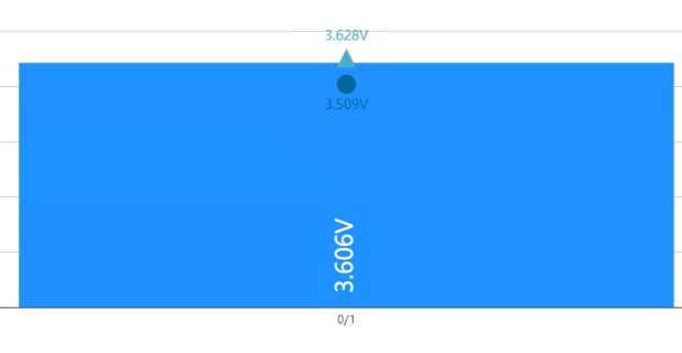
Hey! I now have a few of my packs running with the BMSv4, what do the circle and triangle represent?
The circle I believe is the current voltage as its the same as im reading.