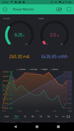
OK… I get a startup flash. One after 6 seconds and nothing. I’ll make another. The 2nd flash suggests the code is working though?
Rick: Great job on the instructional video. I have five controller boards completed and programmed with no issue other than the sixth Wemos board was missing a resistor and errored out on me. I have my first batch of cell monitoring boards ready to program (about 20) and I had failure after failure last night. The Arduino IDE download from the Microsoft store, where it moved the folders to a different location and they are “hidden files”, threw a major wrench into my plans. For everyone else, don’t download from Microsoft store. The pinout on the 2x3 connectors also required some research. It appears that they are “pin-to-pin” from the cell monitoring board to the Arduino after you find Pin 1. It appears that you did not use the ICSP 2x3 connector on the Arduino. Is this correct? I am going to try this again tonight after work and I sincerely appreciate your instructional video.
Hi,
I thought I would just say hello and I would like to pass on my thanks to the developers and all who have contributed to this project.
I have been collecting data on my own home energy usage and have been harvesting cells for a number of years and i’m finally ready to start building and testing a small powerwall. I have decided to use DIYBMS as I love projects where I can get hands on. I’ve created functional circuits and minor electronics projects of my own for most of my life but I have never ordered PCB’s or worked with SMD devices so I am particularly looking forward to this build.
My goal is to build a 14s60p powerwall, I intend to start small and build it modular in maybe 20p packs.
I’ve ordered enough PCB’s and components to make 20 bms boards and 2 control boards.
I’ll share some pictures when I’ve completed my first few boards.
thanks
Neil.
For those using the Arduino, refer to the pinout picture earlier with the MISO, VCC, etc. Pin 2, or VCC, goes to 5V on the Arduino. Pin 5, or RST, goes to 10 on the Arduino, and Pin 6, or GND goes to GND on the Arduino. The remainder are pin-to-pin the same on the 2x3 connectors. After I remedied my wiring error, PlanePilot’s instructions worked perfectly.
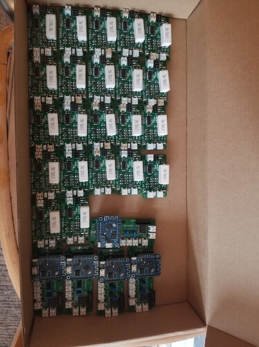
I can no longer “add” to this blog as I have reached my maximum of 20 posts, so I am adding to previous posts. I just wanted to add a pic of first batch of assembled and programmed boards as Stuart request. I guess I will not be replying for a while until my “new user” gets upgraded.
I forgot to order control boards… Is the Geber part of the v4 BMS github or seperate?
That should be fixed now.
Hi, it’s in the github download, but seperate to the main (actual BMS) gerber.
You can find it in : diyBMSv4-master.zip\diyBMSv4-master\ESPControllerCircuit\gerber
Got my relay module this morning, will be testing the diy individual and pack over-voltage protection rules with my victron bluesolar 150/70.
I’ve over come a few issues this week, I finally got the wimos after ordering another it it arriving on Monday. I’ve still not received the original.
1 board wasn’t measuring temp (Constantly read, -041) Turned out R20 was a dry joint.
I’ve also fixed an issue with the wimos constantly disconnecting from the wifi (allowing it internet access fixed that, I guess it was the clock trying to sync).
I now have a stable connection, and 4 (out of 5) working BMS’ Time to build more!
One issue I have yet to overcome is making changes to the Controller settings. I cannot change the influb db settings (Failed to save), I think this is down to the refresh ticks. Does anyone have any ideas on a fix or workaround?
It may be relevant that I’m using the pre-compiled code.
Also if I change the voltage calibration modifier for a module, it appears to change it for the whole bank. Is this expected behaviour?
This project looks awesome, but I’m not sure if it matches my requirements (and I’m also new to hardware electronics, so forgive me if my questions are dumb  ):
):
- whats the max continuous discharge current thru the BMS? is it limited by the chosen MOSFET?
- what could be modified to increase the discharge capacity?
Hope that makes sense!
The maximum continues discharging current is 1A and will stop discharging as soon as the thermistors from the PCB is reading temperatures higher than 70 degrees, to increase the maximum discharge current you will need to change the MOSFET and the power resistors. You can try IRFZ34N with 4r7 20 / 50W resistor and don’t forget about the thermistor to put it on the heatsink (if you will use one for the power resistor) or as close as possible to the power resistor, but you must use a test PCB or redesign the entire PCB because the original one will not take high currents.
Marius, I’ve just come across the same issue that you have. connecting a 5w bulb to the cells resulting in what appears to be the whole BMS system crashing. Restarting them and I’m back on track, unfortunately I don’t have anything that’ll put a load on a 7s pack apart from a bulb.
Did all your problems go away after doing using that DC to DC power supply?
Eventually (if all goes well) I’ll be using a buck convertor to drop from 24ish V to 12 for my purposes, so there will be a device in between the battery and load.
just found this forum pcb’s being made anyone interested in selling surplus components?
hi only premium users please upload to other site
This BMS doesn’t limit the amount of current you can pull from the cells/battery. Thats a job for a relay/contactor for high current loads.
What you can do, is to drive the contactor from the BMS so that switches the load on/off as needed.
The BMS modules were never designed for anything other than the 2.2 ohm 1W SMD resistors as part of the design.
Did you not order these when you built the modules?
Think you may be confused by the original question here - @sunny-g was asking about discharge current thru the BMS - not the balancing current.
You wouldn’t be able to increase the balancing current on the modules as it is not designed for this purpose and the PCB tracks won’t take the extra current.
Once the temperature is reached, the module uses PWM to discharge and keep the temperature constant - it is still balancing at this point, just with a lower current.
Simon using that DC to DC converter made things go well but I don’t know if is a solution because you will be limited by the maximum current of the buck converter.
Stuart I think you didn’t get it right, he is not using a 5w bulb instead of the 2r2 1w resistor, he is using the bulb as a load for the cells pack and is crashing the BMS, you can try a bulb as the load and you will see the problem. But somebody already mentioned that the bulb is creating a spike of current and can be something with that, I’m curious how will behave with other things that they don’t have a soft start and they require a larger current when they start.
As is go for the maximum discharge current the question for sure is about what the module maximum discharge current is for balancing the cell and I mentioned that doing that modifications he need to design a new PCB because this one is made for that 1A maximum discharge current. Because is not making any sense to ask about the maximum discharge current of the battery pack as long as is not giving any details about his pack and that is limited just by the numbers of cells in the pack, the maximum discharge current of the cell and the thickness of the wires he use.
Stuart how is going with the integration of the ACS758 in your BMS? I start to experimenting with INA219, is quite accurate but the maximum voltage is 26V and the current is 3.2A.
Hi Stuart.
Probabally my bad, The BMS’s are built as designed using the 8 SMD resistors, not the single power resister some people use… I was trying to apply a load to my 7s pack to test it by drawing some mah from the battery.
I’m not using a light as discharge resistor.
Sorry my bad wording. I’d take a pic, but I’m at work.

